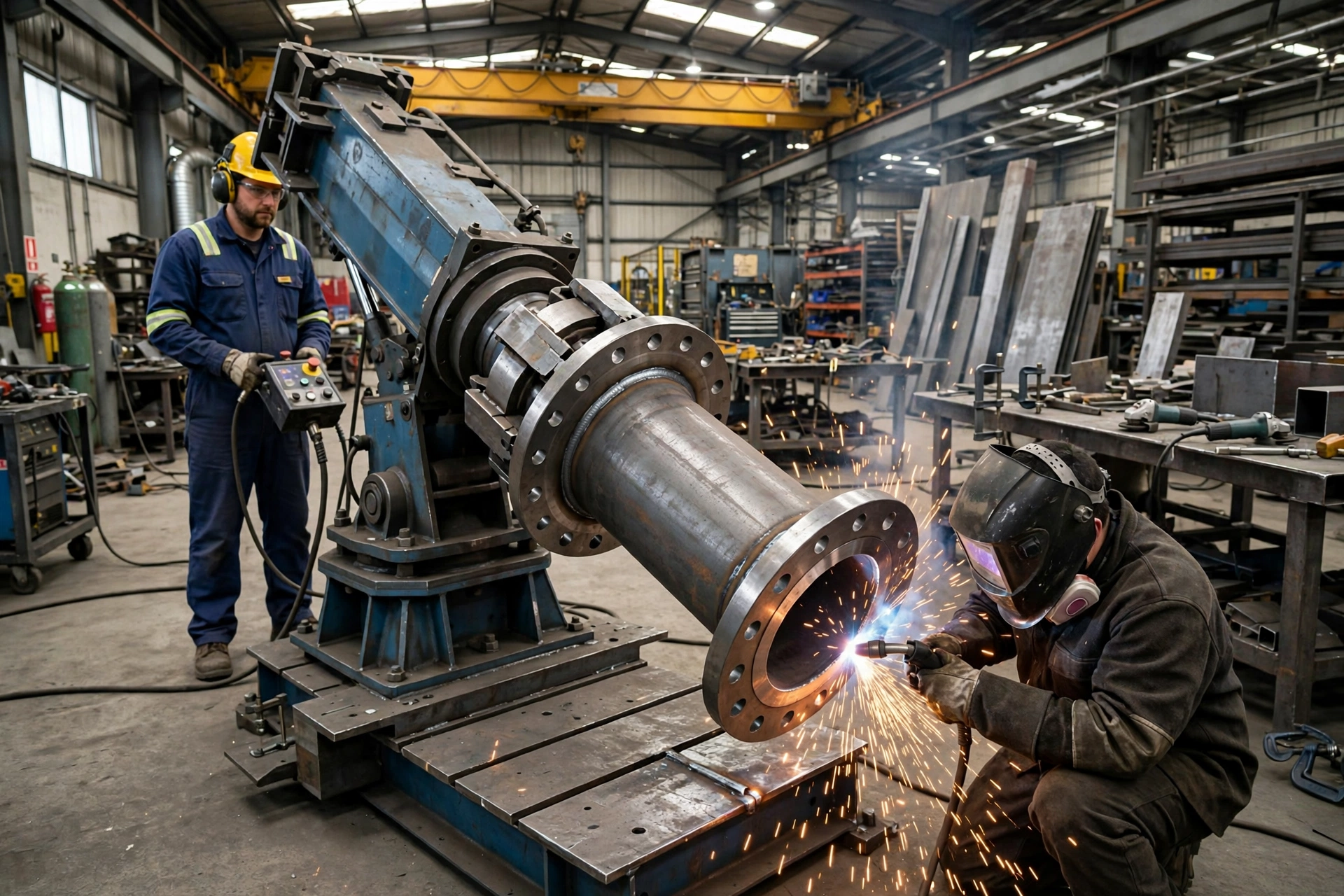
A welding positioner is a powered workholding machine that grips a workpiece — on a faceplate, in a chuck, or between a headstock and a tailstock — and rotates and tilts it so each weld joint can be presented in the flat position to a stationary torch.
A positioner does not support a part on rollers and hope friction turns it. It clamps the part and drives it positively — which is why it can handle the work a rotator cannot: a flanged spool, an elbow assembly, an excavator bucket, a valve body, a frame with joints on four faces. The companion article, What Is a Welding Rotator?, explains the roller route in depth; this article explains the gripping route.
Short Answer
Clamp the work, tilt the joint to flat, rotate it past the torch, then tilt to the next joint — without unclamping.
The workpiece is loaded onto the faceplate and secured with T-slot clamps, chuck jaws, or a dedicated fixture. The operator tilts the table to bring the first joint into the flat (1G/1F) position, then runs the pass while the table rotates at a controlled speed, feeding fresh joint length to the torch without stopping. When that joint is finished, the table tilts to the next one — on another face of the same part — without the workpiece being unclamped or re-rigged.
That in-cycle repositioning is the core advantage over crane handling: the rigging time around each pass disappears. A part with one seam gains little; a valve body or frame with eight joints on four faces gains a great deal, because every joint would otherwise be a separate rigging operation.
MISA builds positioners in the MWP, MEWP and MHWP series, plus headstock-tailstock systems and L-type positioners, with final capacities, tilt ranges, table sizes and lift strokes specified per project. Published MISA project material gives the scale: tilting of 0–120 degrees, rotation of 0–360 degrees, hydraulic lifting of 0–800 mm stroke on a 3-ton example, and a published capacity range of 300 kg to 50,000 kg. Treat those as the range of the family, not the specification of any single model.
Why This Topic Matters
Welding out of position is where a fabrication shop loses money in four places at once: weld quality, rework, cycle time, and safety.
When a welder has to work vertically or overhead, the molten pool fights gravity. Travel speed becomes uneven, the bead profile varies, and the risk of undercut, porosity and lack of fusion rises. Those defects appear later, at non-destructive testing (NDT), as rework — grinding out, re-welding, re-testing, and re-scheduling the next job.
Cycle time suffers the same way: every arc stop for a crane turn means a welder waiting, a crane operator waiting, and a start defect at the next strike. A positioner removes most of that handling from the welding cycle, raising arc-on time — the share of the shift during which the arc is actually burning metal.
It also makes the work safer and less tiring. A welder who is not climbing around a heavy part or working overhead can concentrate on the weld, and a clamped, positively driven workpiece cannot swing, slip off rollers, or shift mid-pass the way a part on a crane sling can.
Technical Background: How a Welding Positioner Works
Rotate, tilt, lift
Most positioners provide two powered motions. Rotation turns the workpiece about the axis through the faceplate, feeding the joint past the torch at a controlled speed. Tilt tips the faceplate about a horizontal axis, bringing a joint on another face into the flat position. A third motion — lifting — raises or lowers the working height, manually (MEWP series) or hydraulically under power (MHWP series). A floor turntable is the boundary case: it rotates but does not tilt.
Why flat-position welding changes the result
Of all the defined welding positions, the flat position — also called downhand, 1G for a groove weld and 1F for a fillet weld — is the easiest to perform and gives the fastest travel speed, the highest deposition rate and the best penetration. Gravity holds the molten pool in the joint instead of pulling it out, so the welder can run hotter and travel faster. The pool is larger, solidifies more slowly, and gases have more time to escape, which reduces porosity. In vertical or overhead positions the pool sags and the bead profile becomes harder to control.
The tilt angles are concrete: a pipe-to-flange assembly tilted to 45 degrees presents its fillet joint in the flat position; joining two pipes end to end needs 90 degrees. Those two numbers are a useful first check on any positioner: can it reach the tilt your joints need, at the load they impose?
How the workpiece is held
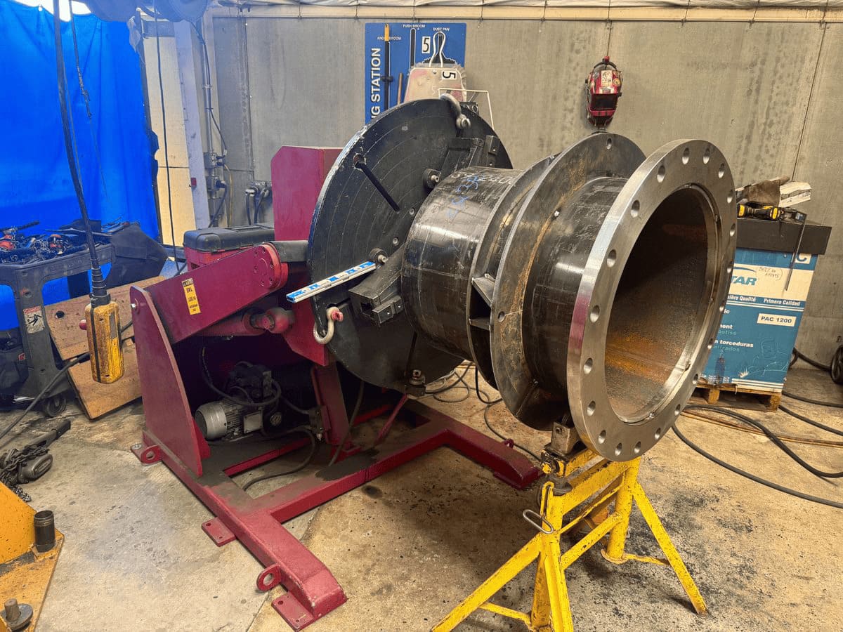
A positioner grips the workpiece positively, usually with a T-slot faceplate and clamps, a three-jaw or four-jaw chuck, or a dedicated fixture. Headstock-tailstock systems grip long work at both ends: a powered headstock drives the part and a tailstock supports the far end. MISA's Perth project, a 3-ton headstock-tailstock positioner for elbow pipe and flanged piping, used a headstock with 5-ton rotation capacity and a 1,500 mm faceplate with 6 T-slots.
That positive grip is the whole difference from a rotator, which depends on friction between the workpiece outside diameter and driven rollers. A positioner does not depend on the outside diameter at all — which is why a flanged spool, a bucket, or a frame with no cylindrical surface can be positioned at all.
Speed, control and grounding
Rotation speed is set by the welding process and the joint diameter, not by preference: the speed of the joint surface passing under the torch must stay in the process window, so a large-diameter joint needs a much slower rotation speed in revolutions per minute (rpm) than a small one. The conversion is surface speed divided by circumference equals rpm. Koike's worked example: a 1,520 mm diameter workpiece welded at a surface speed of 5 mm/s needs a table speed of only 0.064 rpm, about 3.84 revolutions per hour.
Speed must also stay constant under an eccentric load. An elbow or offset branch exerts a varying gravity moment as it rotates, speeding the table up at the 12 o'clock position and slowing it at 6 o'clock. Variable-frequency drives (VFDs) with dynamic braking hold a constant speed through that variation, because a varying surface speed means varying heat input.
Control is usually a wired pendant, a wireless pendant, or a foot switch/panel, with PLC control where the positioner must synchronise with a manipulator or a robot; specify the interface at the order stage if the cell will be automated. And welding current must return through a proper grounding path, not through the bearings: on small positioners, a grounding capacity of 200 A or more is a good rule of thumb, with the ground lead attached to the stud provided.
Main Comparison / Selection Logic: Positioner vs Rotator vs Manipulator
This table matters because it stops the reader buying the wrong family of machine. Price and tonnage do not decide the family. Geometry and how the workpiece is held decide it — and the four machines in the table solve the same basic problem, getting the joint into the right position, in four different ways.
| Machine | What moves | How the workpiece is held / driven | Best for | Wrong choice when |
|---|---|---|---|---|
| Welding positioner | Workpiece, gripped, rotated and tilted | Positively, via faceplate, chuck, or between headstock and tailstock | Flanged, asymmetric or complex work clamped and brought to flat: flanged spools, elbow assemblies, buckets, valve bodies, frames | The part is long and unsupported (cantilever load); or very heavy and cylindrical, where rollers are cheaper per tonne |
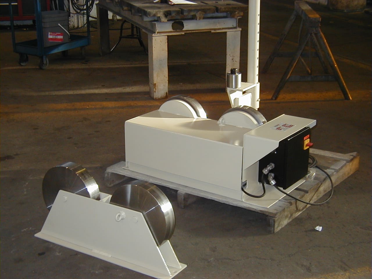
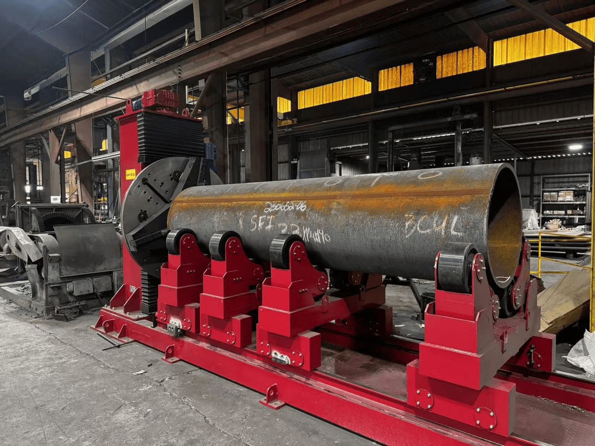
| Welding rotator (turning rolls) | Workpiece, supported and rotated only | By friction between the outside diameter and driven rolls; no grip, no tilt | Cylindrical work — pipes, tanks, shells, pressure vessels, wind tower sections; circumferential seams | The section is non-cylindrical, flanged or offset, or varies in diameter so the rolls lose contact |
| Column-and-boom manipulator | Welding head, not the workpiece | Torch is carried on a vertical column and horizontal boom; workpiece stays put | Large or heavy work that cannot practically be rotated; long longitudinal seams | The joint needs the workpiece to turn; the torch alone cannot bring it to flat |
| Floor turntable | Workpiece, on a faceplate, rotated about a vertical axis | Carried on a face; load runs down through a vertical axis | Heavy, any-shape work loaded from above; disc, ring, flange or vessel-head work | The joint also needs to be tilted into the flat — a turntable has no tilt axis |
After the table, the conclusion is simple: ask first how the workpiece must be held, and only then how heavy it is. A positioner grips the workpiece and drives it positively; a rotator depends on contact between the workpiece outside diameter and its rolls; a manipulator does not move the workpiece at all.
In practice the machines are often used together: a positioner holds and tilts the part while a column-and-boom manipulator carries the torch. For pipe spool work, the geometry-first rule from the RESIZE guide is the shortest version of this table: supported, cylindrical pipe that can turn takes a rotator; clamped pipe takes a positioner; fixed pipe takes an orbital system.
Sizing: payload, torque and centre-of-gravity envelope
A positioner is not sized by its headline tonnage. It is sized by three numbers together.
Payload is the total mass the machine carries: workpiece plus fixture plus chuck plus any adapter. A heavy fixture or a large chuck can add hundreds of kilograms. Weigh the fixture or calculate it; do not estimate it.
Torque is what the tilt and rotation drives actually have to overcome, in two forms checked separately. Tilt torque is the weight multiplied by the distance from the table surface to the centre of gravity, plus any inherent overhang, measured perpendicular to the tabletop. Rotation torque is the weight multiplied by the distance from the centre of the table to the centre of gravity, measured parallel to the table surface. Both must sit inside the machine's rated tilt and rotation torque. A part can be inside the weight rating and outside the torque rating at the same time; the overload lands on the tilt gear, the rotation drive and the slewing bearing, and appears later as backlash, noise, or a damaged gear tooth.
Centre-of-gravity offset and height are two different limits. Offset is how far the combined centre of gravity of workpiece and fixture sits from the rotation axis, measured in the plane of the faceplate. Height is how far that centre of gravity sits above the faceplate, along the rotation axis. The two are not interchangeable: a workpiece can sit inside the rated load and still be outside the machine's rated offset. Mount the part so its centre of gravity is as close to the table's centre of rotation as fixturing allows.
Swing radius is the clearance the part needs to complete its motion. When the table is fully tilted, the workpiece must swing above the floor without hitting it, a wall, or the operator's station. For larger workpieces the answer is a raised table — a manually adjustable base, a powered elevating base, or a riser/sub-base.
Worked example: what an offset centre of gravity actually costs
This is an example with stated assumptions, not a MISA specification. Use your own mass and offset in its place.
Torque is force multiplied by the perpendicular moment arm. Take a 1,000 kg assembly — a flanged spool with its fixture — whose combined centre of gravity sits 0.30 m from the rotation axis. Its static gravity moment is 1,000 kg × 9.81 m/s² × 0.30 m = 2,943 N·m. Move the same assembly so its centre of gravity sits 0.60 m from the axis and the moment doubles to 5,886 N·m, even though the mass has not changed.
That doubling is the point: a lighter spool with a large offset can impose a greater gravity moment than a heavier, nearly concentric cylinder. When you send an RFQ, send the offset and the height with the weight. A supplier who sizes a positioner from weight alone is guessing at the torque, and the torque is what breaks machines.
If your joint needs the table at 45 degrees to reach flat, ask for the rated load at 45 degrees — not the maximum tilt angle and the maximum load as two independent numbers.
Types of Welding Positioner
There are five structures that matter for a buyer, differing in how the workpiece is held and whether the working height can be adjusted.
Standard tilt-and-rotate (MWP series). The default machine: a horizontal T-slot faceplate, rotating about a vertical axis and tilting about a horizontal one, typically through 0–120 degrees. For flat-based work — flanges, valve bodies, plate assemblies, vessel heads.
Manual lifting (MEWP series). A tilt-and-rotate turntable whose lift is set by hand, with the working height fixed once set. Suits shops where the height stays constant across a production run.
Hydraulic lifting (MHWP series). The same elevating turntable, with the lift under power as a third axis. MISA's published example is a 3-ton hydraulic positioner that rotates 0–360 degrees, tilts 0–120 degrees and lifts through a 0–800 mm stroke, supplied to a heat-transfer equipment manufacturer in Camden, NJ, USA, for pipe and flange work. The right choice where working height has to change between jobs.
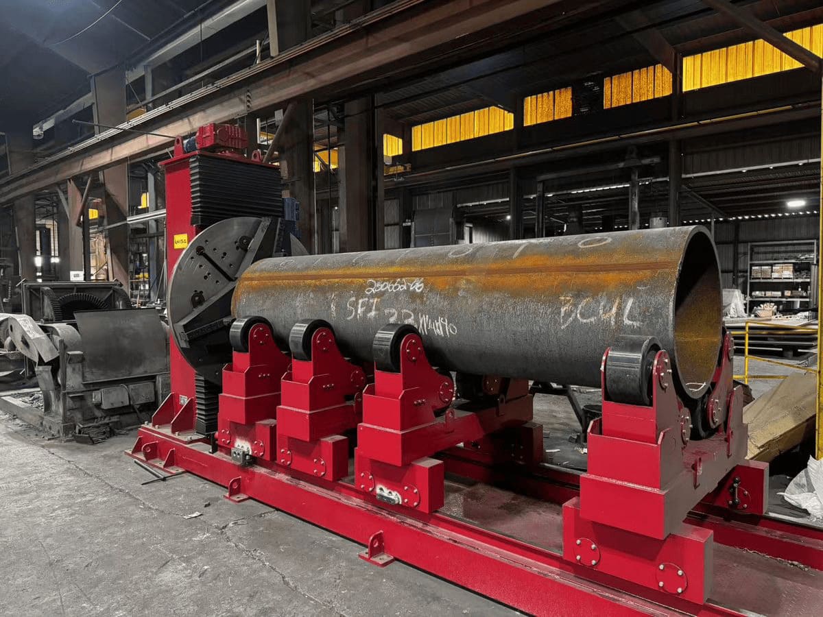
Headstock-tailstock. Two units facing each other: a powered headstock with a faceplate or chuck, and a tailstock supporting the far end. The workpiece is driven positively from one end rather than by friction, which suits long parts and sections that are not a constant circle, and supporting both ends removes the cantilever bending load of a single faceplate.
L-type. An L-shaped, three-axis configuration built for large, asymmetric fabrications with many seams on many faces — above all, excavator buckets. MISA's Belfast project, a 5-ton L-type positioner for a Northern Ireland manufacturer of heavy-duty excavator buckets, gave 360-degree rotation and −180 degrees to +180 degrees of tilt, with lifting available as an addition. MISA notes that around 90% of its customers use this kind of positioner for bucket work.
The table below compares the five structures directly. Read it as a choice by workpiece geometry and workflow, not by which type is newest.
This table matters because the structures look similar in a photograph and very different in a working day.
| Type (MISA series) | Structure & axes | Tilt & lift | Best for | Watch out for |
|---|---|---|---|---|
| Standard tilt-and-rotate (MWP) | Faceplate with T-slots; rotation + tilt (2 axes) | Tilt 0–120° in published project material; no lift | Flat-based, clampable work: flanges, valve bodies, plate assemblies, vessel heads | Long or tall work becomes a cantilever; check CG height and swing radius |
| Manual lifting (MEWP) | Tilt-and-rotate turntable + manual lift | Tilt + manual lift, height fixed once set | Shops where working height stays constant | Height changes cost a manual reset; not for frequent changeover |
| Hydraulic lifting (MHWP) | Tilt-and-rotate turntable + powered hydraulic lift (3 axes) | Tilt 0–120°, lift 0–800 mm stroke on published 3-ton example | Pipe and flange work; frequent height changes | Powered lift adds cost and maintenance; skip it if height never changes |
| Headstock-tailstock | Powered headstock + supporting tailstock, workpiece held at both ends | Rotation 0–360°; tailstock movable on rail for length | Long pipe, shafts, elbow-pipe and flanged spools | Needs grippable ends and floor length for the rail |
| L-type | L-shaped frame, rotation + wide tilt, lifting optional (3 axes) | Rotation 360°, tilt −180° to +180° on published 5-ton bucket example | Excavator buckets and large asymmetric fabrications | Largest footprint; overkill for a single-face part |
After the table, the buyer conclusion is: match the structure to the geometry and to how often the height changes, and do not pay for a third axis you will never move. A standard MWP covers most clampable work, a headstock-tailstock covers long work, an L-type covers buckets, manual lifting covers a fixed height and hydraulic lifting covers a changing one. If you cannot say which describes your work, send the drawing — the structure follows from the drawing, not from the catalogue order.
Application Matrix: Which Workpiece Goes on a Positioner?
This table maps workpiece geometry to the equipment route. It matters because it turns the definition into a decision you can apply to the next job on your shop floor, without re-reading the theory each time.
| Workpiece / application | Recommended route | Why | MISA-relevant option |
|---|---|---|---|
| Flanged pipe spool needing reorientation | Welding positioner, standard or headstock-tailstock | Fixture connection, required tilt, access to each joint; rollers cannot grip a flange | Welding positioner (MWP or headstock-tailstock) |
| Elbow or offset branch assembly | Clamped positioner, or purpose-designed support | Centre of gravity moves through the motion; rollers cannot grip it | Welding positioner; check CG offset and swing radius |
| Excavator bucket or other asymmetric fabrication | Welding positioner, L-type or hydraulic | Must be tilted and rotated to bring each joint to flat; many seams on many faces | L-type positioner; see welding positioner for bucket |
| Pressure-vessel part, nozzle or vessel head | Welding positioner, plus manipulator | Nozzles and heads need tilt as well as rotation; torch travel helps on long seams | Positioner + column-and-boom manipulator |
| Pipe spool, straight and cylindrical | Welding rotator, not a positioner | Rollers can support and turn it through full rotation; no fixture needed | Welding rotator, drive + idler |
| Long pipe or shaft needing support at both ends | Headstock-tailstock positioner | Removes cantilever load; driven positively from one end | Headstock-tailstock positioner |
| Large flat or structural assembly that cannot be lifted onto a table | Column-and-boom manipulator, torch moves | Workpiece stays put; torch travels to the joint | Welding manipulator |
| Heavy disc, ring or flange loaded from above, rotation only | Floor turntable | Load runs down through a vertical axis; no tilt needed | Turntable (rotation only) |
| Pipe that cannot rotate | Orbital head or another qualified fixed-pipe process | Head envelope, clamping length and joint access decide it | Special welding equipment, by project |
After the table, the buyer conclusion is: cylindrical, roller-supported work is rotator work. Flanged, offset or asymmetric work is positioner work. Work that cannot move at all needs a manipulator to bring the torch to it.
MISA project evidence: Auckland, New Zealand (June 2019) — 5-ton positioner and 10-ton turntable; Belfast, UK (April 2017) — 5-ton L-type for excavator buckets; Camden, NJ, USA (October 2017) — 3-ton and 5-ton hydraulic positioners; Perth, WA, Australia (December 2018) — 3-ton headstock-tailstock positioner. See the full list on MISA's welding positioner projects page.
Cost / ROI / Total Cost Factors
Do not compare positioners by purchase price alone. Compare them by cost per seam, including handling, rework and crane time. The table below shows the direction of each cost driver — a framework for your own quotation comparison, not a price list.
This table matters because the cheapest positioner in the quotation is often the most expensive machine in the shop: if it cannot tilt to the angle your joints need, or cannot carry the offset your part imposes, it saves nothing and still has to be replaced.
| Cost driver | Manual / crane positioning | Positioner, manual welding | Positioner + manipulator, automated cell |
|---|---|---|---|
| Equipment capex | Lowest | Medium | Highest |
| Arc-on time | Lowest; arc stops for every reposition | Higher; continuous rotation, tilt between joints without unclamping | Highest; torch and workpiece move together |
| Labour per seam | Highest; welder waits, crane operator waits | Lower; operator controls speed and tilt from pendant | Lowest per seam at volume; operator supervises the cell |
| Rework and NDT failures | Highest; out-of-position variation | Lower; consistent flat-position heat input | Lowest; repeatable process, if the procedure is correct |
| Crane time | Highest; crane turns the work | Lower; crane only loads and unloads | Lowest; cell layout can reduce crane dependency further |
| Floor space | Lowest | Medium; positioner footprint plus swing clearance | Highest; cell layout, rails and manipulator envelope |
| Training and maintenance | Lowest | Medium; VFD, motors, tilt gear, hydraulics where fitted | Highest; PLC, synchronisation and integration |
After the table, the conclusion is: a positioner pays back when handling time and rework, not arc time, dominate your cycle. A part with many joints on many faces pays back fastest, because every joint is a repositioning step saved; a part with a single seam may never pay back. Westermans cites industry data suggesting welding productivity can improve by up to 70% when a positioner is introduced into a repetitive or heavy-duty process; treat that as an industry-data claim, not a guarantee. Work the example in your own numbers: count joints per part, repositioning time per joint, crane time per part, and rework rate before and after automation.
When Not to Use a Welding Positioner
A positioner is not the right machine for every welding job. Do not use a standard single-faceplate positioner as the first choice when:
- The workpiece is long and unsupported. One-end gripping creates a cantilever load: the part sags and the joint wanders. Use a headstock-tailstock system or add auxiliary supports.
- The work is very heavy and cylindrical. A 20-ton or 60-ton vessel section that can sit on rollers is usually cheaper per tonne on a rotator and needs no fixture at all.
- The joint needs rotation only, and no tilt. A floor turntable does that job more simply and usually more cheaply. Do not buy a tilt axis you will never move.
- The work must stay fixed. A pipe that cannot rotate — because it is already installed, connected, or too large to move — needs an orbital head or another qualified fixed-pipe process, not a positioner.
- The part's swing radius exceeds your floor clearance. An asymmetric part tilted to flat can hit the floor, a wall or the operator's station. Decide on a raised table, a pit, or a different layout before ordering.
- The centre-of-gravity offset exceeds every available frame. Some parts are simply too eccentric for a faceplate machine at any sensible size. A purpose-designed fixture, counterweighting, or a different holding method may be needed — and counterweighting is not a universal fix.
If any of these apply, the right next step is not a larger positioner. It is a different machine, or a different cell layout — see MISA's welding rotator and welding manipulator pages.
Common Buying Mistakes
- Choosing only by rated tonnage. A 5-ton positioner does not automatically handle every 5-ton workpiece safely. Centre-of-gravity offset, height and torque can make the same weight unsafe.
- Ignoring centre-of-gravity offset and height. A part inside the weight rating can still be outside the offset rating — doubling the offset doubles the gravity moment at the same mass. The overload appears later as backlash, noise or a damaged gear tooth.
- Confusing maximum tilt angle with rated load at that angle. A machine may tilt to 120 degrees but be rated for full load only to a lower angle. Ask for the rated load at the angle your joint needs.
- Buying a positioner for long unsupported work. One-end gripping creates a cantilever load, the joint wanders, and the bearings suffer. The cost is the rework, the delay, and the headstock-tailstock system you have to buy anyway.
- Buying a rotator or a turntable when the joint also needs tilt. Neither has a tilt axis, so the joint never reaches flat and the original problem survives the purchase.
- Forgetting the fixture, chuck and adapter in the payload. The rated load is workpiece plus fixture. An unweighed fixture plate or a large chuck can push the real load over the rating.
- Ignoring swing radius and floor clearance. An asymmetric part tilted to flat needs room to swing. If it hits the floor, the machine cannot complete its rotation, and the fix is far more expensive after delivery.
- Ignoring rotation-speed range for the process. Speed must match surface speed at the joint diameter. A machine whose speed range does not cover your largest diameter cannot weld that diameter correctly, and the failure shows up as NDT failures.
- Ignoring voltage, CE marking and local safety rules. MISA configures electrical systems for 110 V to 600 V across its welding automation range, with adaptation to local safety rules and standards. A machine built for one country's power and safety rules is not automatically compliant in another country.
- Ordering without a drawing, joint list or production target. Without the workpiece drawing, joint types and parts per week, the supplier cannot size the drive, the tilt gear or the duty cycle. You will get a catalogue recommendation, not a specification for your shop.
Buyer Checklist
- What is the workpiece weight, dimensions and shape — including flanges, nozzles and attachments? Shape decides the family, dimensions decide the table and the swing.
- Where is the combined centre of gravity (workpiece + fixture + chuck), offset and height? Offset and height set tilt and rotation torque and the real safe capacity.
- What tilt angle does each joint need to reach flat, and what load is rated at that angle? Maximum tilt and maximum load are separate figures.
- What is the swing radius when the part is fully tilted? Swing decides floor clearance and whether the part can complete its rotation.
- What joint types do you need to weld? Circumferential, longitudinal and fillet joints need different torch access. List every joint, not just the largest one.
- What weld process will you use? MIG/MAG, TIG, SAW and FCAW have different travel speeds, heat inputs and torch access needs. The rotation-speed range must match the process.
- What surface speed and rotation-speed range do you need? Speed sets heat input. Confirm the range covers the surface speed at your largest joint diameter.
- How will the workpiece be held — T-slot faceplate, chuck, or dedicated fixture? Workholding decides usable capacity and changeover time. State it in the RFQ.
- How often must working height change — is manual lifting (MEWP) enough, or is hydraulic lifting (MHWP) needed? Frequency of height change decides whether a powered third axis is worth its cost.
- What control do you prefer — wired pendant, wireless pendant, foot switch/panel, or PLC? Control affects operator position, safety and cell integration.
- What is your production target — parts per week, joints per part, cycle time per part? It decides whether a manual positioner, a semi-automatic set or a fully integrated cell is the right investment.
- What floor space, crane capacity and loading path do you have? A positioner that cannot be loaded, swung or reached by the crane will sit idle.
- What existing rotator, manipulator, positioner or robot must it integrate with? Integration decides synchronisation, control and layout.
What to Send for a Quote
Send MISA the following with your RFQ. The more of it you send, the less the quotation has to guess.
| RFQ field | Why MISA needs it |
|---|---|
| Workpiece drawing, with flanges, nozzles and attachments | Decides family, structure, fixture and swing |
| Dimensions, weight, and shape | Sizes frame, table diameter and drive |
| Centre of gravity — offset and height, workpiece + fixture + chuck | Sizes tilt and rotation torque; checks the CG envelope |
| Joint list and tilt angle needed per joint | Decides tilt range and load at that angle |
| Weld process and power source | Sets speed range and heat input |
| Required surface speed and rotation-speed range | Sizes VFD, motor and drive ratio |
| Workholding — T-slot faceplate, chuck, or dedicated fixture | Decides usable capacity and changeover time |
| Lift requirement — manual or hydraulic, and stroke | Decides MEWP vs MHWP |
| Control preference — wired, wireless, foot switch/panel, PLC | Decides pendant and cell layout |
| Power supply, voltage, and local safety rules | Decides electrical configuration and CE marking |
| Floor space, swing clearance, and crane capacity | Checks loading and layout are possible |
| Existing equipment on site | Checks integration and synchronisation |
| Production target — parts per week, joints per part, cycle time | Decides manual vs semi-automatic vs integrated cell |
| Drawings, quantity, delivery location and date | Prices the system, not just the positioner |
For the product itself, see MISA's welding positioner page, for project evidence see welding positioner projects, and for the bucket application see welding positioner for bucket. For the torch-moving partner machine, see the welding manipulator. To learn more about MISA itself, see about MISA.
Final Recommendation
A welding positioner is the right machine when your work must be gripped, rotated and tilted so every joint can be welded in the flat position — flanged spools, elbow assemblies, buckets, valve bodies, and frames with joints on more than one face.
Choose the structure by geometry and workflow, not by catalogue order. Standard tilt-and-rotate (MWP) for clampable work. Manual lifting (MEWP) when the working height stays fixed. Hydraulic lifting (MHWP) when it changes between jobs. Headstock-tailstock when the work is long and needs support at both ends. L-type for buckets and large asymmetric fabrications. Choose a rotator instead when the work is cylindrical and can sit on rollers, and a manipulator when the work cannot move at all.
Do not order by tonnage alone. Order by payload including the fixture, centre-of-gravity offset and height, tilt angle and the load rated at that angle, swing radius, rotation-speed range, workholding, lift method, control, power, and production target — in writing, in the RFQ. Send MISA your workpiece drawing, joint list, centre-of-gravity data and production target, and ask for the rated load at the tilt angle you need, the centre-of-gravity limits, the tilt and rotation ranges, the lift stroke, the speed range, the control package, the voltage, and the CE documentation.
Sources and further reading
- MISA, Welding Positioner Projects — Auckland, Belfast, Camden and Perth examples, 300 kg–50,000 kg range: https://weld-fab.com/welding-positioner-projects/
- MISA, Welding Positioner for Bucket — bucket welding, chuck and T-slot fixing: https://weld-fab.com/welding-positioner-for-bucket/
- MISA, Welding Positioner — product page (note: on 2026-11-14 this page rendered manipulator content under the positioner heading): https://weld-fab.com/welding-positioner/
- MISA, Welding Rotator — companion article's rotator reference: https://weld-fab.com/welding-rotator/
- MISA, Welding Manipulator — column-and-boom stroke, processes, PLC synchronisation: https://weld-fab.com/welding-manipulator-2/
- Koike, How to Size a Positioner — torque, centre of gravity, swing radius, surface speed: https://www.koike.com/how-to-size-a-positioner/
- Westermans, Welding Positioners: The Complete Guide — types, weld quality, productivity, selection: https://www.westermans.com/knowledgehub/welding-positioners-guide.aspx
- The Fabricator, Putting the spin on benchtop positioners — flat position, 45°/90° tilt, grounding, speed: https://www.thefabricator.com/thefabricator/article/arcwelding/putting-the-spin-on-benchtop-positioners-for-tube-and-pipe-welding
- RESIZE, Welding Equipment for Oil and Gas Pipe: Spool Setup — geometry-first rule, torque worked example: https://resizeweld.com/blog/oil-gas-pipe-welding-equipment/
MISA project figures in this article are MISA-published project examples for stated conditions. The torque worked example (1,000 kg, 0.30 m offset = 2,943 N·m) is an example with stated assumptions, credited to RESIZE. The "up to 70%" productivity figure is an industry-data claim cited by Westermans, not a MISA measurement. Confirm capacity, centre-of-gravity limits, tilt range, load at angle, speed range, voltage and CE documentation for the exact model you order.
Restored legacy detail
Welding Positioner Guide: Types, Uses & Selection
Most positioner enquiries start with the wrong question. "Which machine do I need for a two-tonne workpiece?" cannot be answered, because the same two tonnes behaves completely differently depending on where its centre of gravity sits, how far the joint has to tilt, and how far the workpiece overhangs the table.
Most positioner enquiries start with the wrong question. "Which machine do I need for a two-tonne workpiece?" cannot be answered, because the same two tonnes behaves completely differently depending on where its centre of gravity sits, how far the joint has to tilt, and how far the workpiece overhangs the table.
A welding positioner holds a workpiece on a rotating faceplate or chuck and tilts it, so a joint can be presented in the flat or horizontal position. It moves the work, not the torch. Where a component is currently turned between passes by crane, or welded out of position because there is no way to bring the joint round, the positioner replaces handling time and positional welding with a flat, repeatable joint.
This page is written for specification and procurement rather than first principles. If you are new to the equipment and want the underlying explanation of what a positioner is and how it functions, start with our beginner's guide to welding positioners and return here for the sizing work.
Related search terms
1. What a welding positioner does
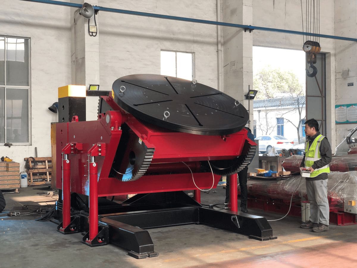
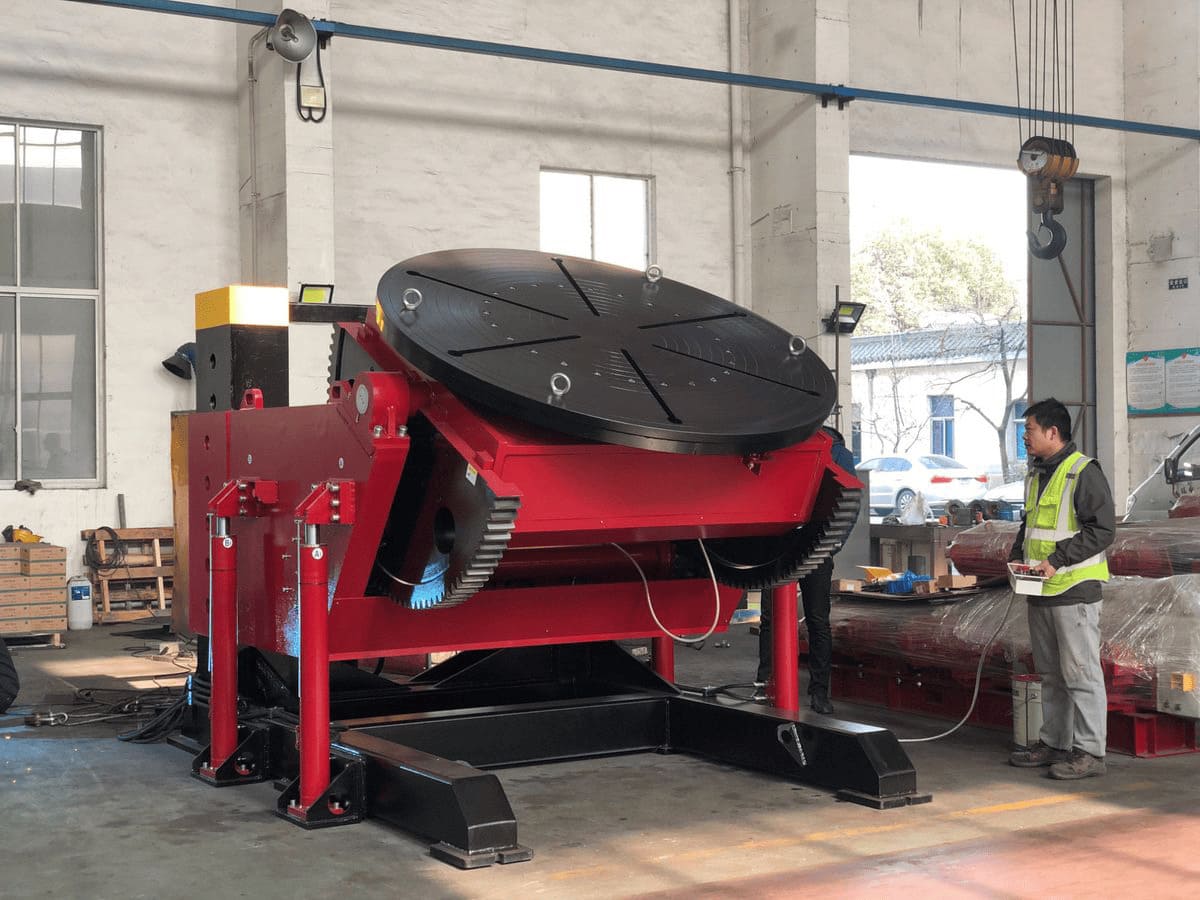
A positioner is a motorised workholding machine. It rotates the workpiece about an axis through the faceplate, and on most configurations tilts that faceplate from horizontal through to vertical or beyond, to bring a joint into the flat (1G/1F) or horizontal (2G/2F) position — where deposition rate, bead profile and operator control are all at their best.
The distinction that matters at the point of purchase is how the workpiece is held. A positioner grips it — on a faceplate, in chuck jaws, or between a headstock and a tailstock — which is what allows it to handle flanged, asymmetric and non-cylindrical work that cannot simply be laid on rollers.
A positioner moves the workpiece to the torch by gripping it. A welding rotator also moves the workpiece, but supports it on driven rollers and can only rotate it. A column-and-boom manipulator moves the torch instead. In an automated cell the positioner and the manipulator are usually specified as a pair, because the rotation speed and the torch travel have to be coordinated.
2. How it works in a production cycle
The workpiece is loaded onto the faceplate and secured with T-slot clamps, chuck jaws or a dedicated fixture. The operator tilts the table to bring the first joint to the flat position, then runs the pass; rotation at the programmed travel speed feeds fresh joint length to the torch without stopping. When that joint is finished, the table tilts to the next one without the workpiece being unclamped.
That in-cycle repositioning is the core advantage over crane handling: the rigging time around each pass disappears, and the setup repeats identically on the next part. What it is worth depends on the component. A part with one circumferential seam gains little, because there is only one repositioning step to save. A valve body or a fabricated frame with eight joints on four faces gains a great deal, because every one of those would otherwise be a separate rigging operation. This is why the same machine pays back in weeks on one product line and never on another.
3. Configurations MISA builds
Positioner catalogues use overlapping names, and the result is that buyers compare machines that are not comparable. MISA's range falls into three mechanical families. Tilt and rotation are common to all of them; what changes is how the workpiece is held, and whether the working height can be adjusted.
3.1 Standard tilting turntable — MWP series
A horizontal faceplate with T-slots, rotating about a vertical axis and tilting about a horizontal one. This is the default configuration for flat-based work: flanges, valve bodies, plate assemblies, vessel heads. MISA builds it as the MWP series in two-axis form — rotation and tilt — from 1 to 10 tonnes.
3.2 Elevating positioners — MEWP and MHWP series
These are turntables that can also be raised, and they are the category most often mis-described in comparison tables. Both are elevating positioners; the difference between them is how the lift is achieved, not what the machine is for.
- MEWP series — manual elevating, two-axis (rotation and tilt). The lift is set by hand and the working height is fixed once set. Suitable where the table height stays constant across a production run.
- MHWP series — hydraulic elevating, with the lift under power as a third axis. Suitable where the working height has to change between jobs, or where a heavy table has to be repositioned frequently.
The purchase decision between them is about how often the working height changes, how the workpiece is loaded at each height, and whether the operator can reasonably set the height manually at the start of a run. It is not a question of one being more "advanced" than the other. Confirm the axis count and lift method for the specific model being quoted, since these are stated per model rather than uniformly across a series.
3.3 Headstock and tailstock positioners
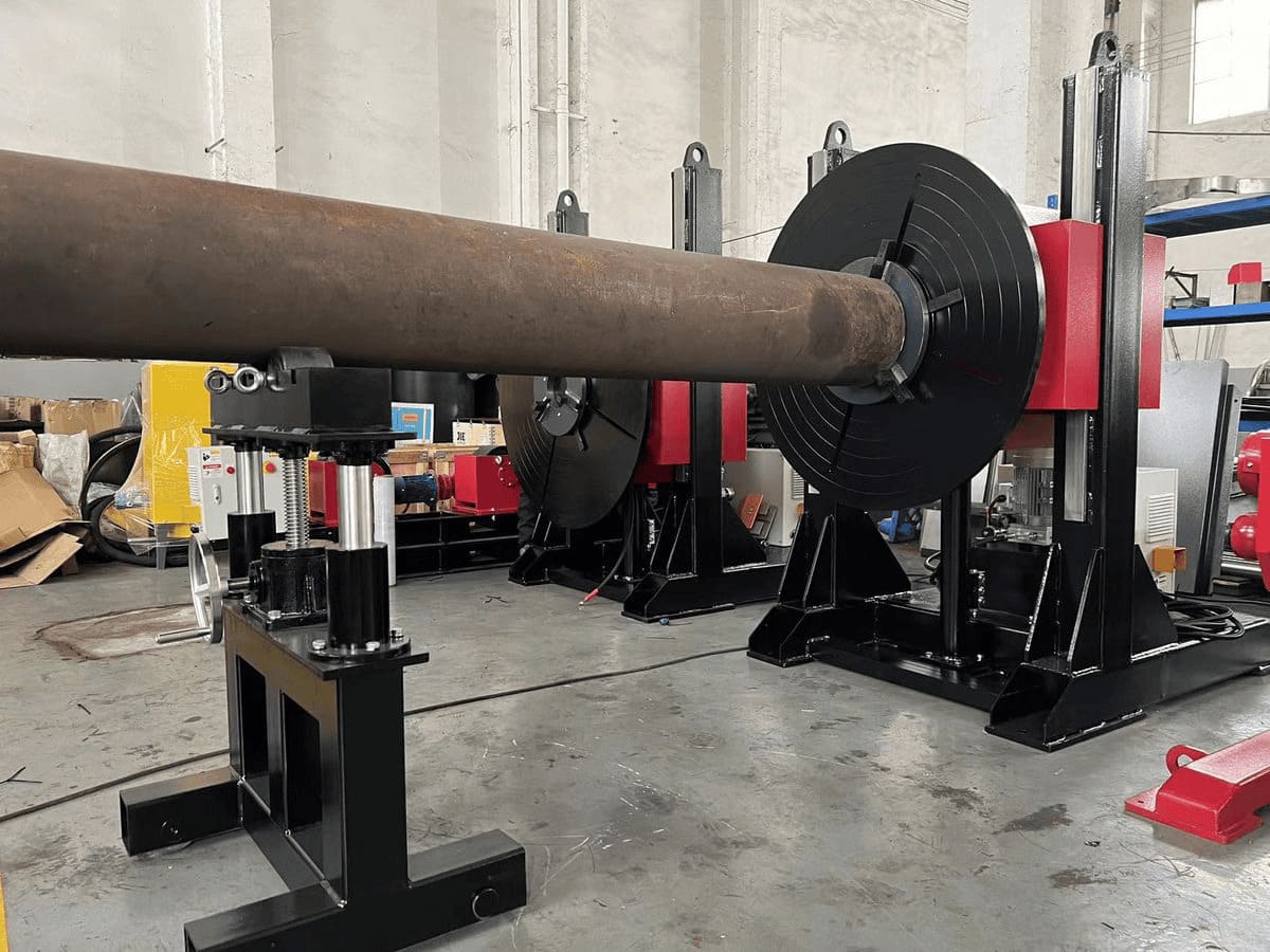
Two units facing each other: a powered headstock with a faceplate or chuck, and a tailstock that supports the far end. The workpiece is driven positively from one end rather than by friction on its outside diameter, which is what makes the configuration suitable for long parts, and for sections that are not a constant circle. Supporting both ends also removes the cantilever bending load that a single faceplate imposes on a long workpiece. See the headstock and tailstock range.
Whether a long workpiece needs this arrangement depends on more than its length. A long part may also be run on a positioner with suitable auxiliary supports, depending on its weight, its centre of gravity, and whether the joint has to be rotated through a full turn. The choice follows from the load path, not from a length threshold.
3.4 Other configurations built to order
Beyond these three families, MISA builds floor turntables for flush-floor installations, chuck-based positioners for pipe and fittings held in jaws, and special fixtures and frame geometries developed against a workpiece drawing. If your workpiece does not fit a standard configuration, the specification is developed from the drawing rather than selected from the range.
4. Specifications that decide the purchase
Load capacity is quoted per axis, not once
Positioner datasheets state a rated load, but what that figure applies to depends on the axis. On MISA's MWP-10 the load carrying, rotation and tilting capacities are all quoted at 1,000 kg. On the MWP-50 the tilting capacity is quoted at 90°, while the series specification lists a tilt range extending to 120°. Those are two different statements, and the gap between them is where buyers get caught.
A machine may tilt to a stated maximum angle without being rated for full load at that angle. Above the angle at which tilting capacity is quoted, expect the permissible load to reduce.
Always ask for the rated load at the specific angle your joint requires, not the maximum tilt angle and the maximum load as two independent numbers. For the MWP-50 these figures should be confirmed with MISA for the exact configuration being quoted.
Centre-of-gravity offset and centre-of-gravity height are two different limits
Most buyers check weight and stop. Two further limits govern whether the machine will survive the duty:
- Centre-of-gravity offset — how far the combined centre of gravity of workpiece and fixture sits from the rotation axis, measured in the plane of the faceplate. This is the radial distance that creates the overturning moment on the rotation bearing and tilt gear.
- Centre-of-gravity height — how far that centre of gravity sits above the faceplate, along the rotation axis. This loads the assembly differently, and the two limits are not interchangeable.
MISA's MWP-10, MWP-50 and MWP-100 datasheets each state a maximum centre-of-gravity height of 200 mm and a maximum centre-of-gravity offset of 200 mm. They are listed as separate parameters because they describe separate directions of loading. Confirm the definition used for the axis in question against the current datasheet before you apply either figure.
The practical consequence: a workpiece can sit comfortably inside the rated load and still be outside the machine's rated offset. A 2,000 kg component on an MWP-50 is 40% of the 5,000 kg rating. If the fixture puts its centre of gravity 350 mm off the rotation axis, the machine is now carrying an offset it was not rated for — and the overload lands on the rotation drive, the tilt gear and the slewing bearing rather than on the frame. It does not announce itself. It appears later as backlash, noise, or a damaged gear tooth.
Potential options, subject to engineering review: redesign the fixture so the workpiece sits closer to the rotation axis; add a counterweight on the opposite side to bring the combined centre of gravity back within range; or move to a larger frame rated for the offset. Counterweighting is not a universal fix — it adds mass to the machine and has to be evaluated against the tilt duty as well as the rotation duty. The calculation should include the fixture plate, chuck and any adapter, not the workpiece alone.
Table size and rotation speed
Table diameter has to clear the workpiece, not match it. Overhang beyond the table is not inherently unsafe, but the overhanging mass becomes offset load — which returns you to the previous section. Rotation speed is set by the welding process, not by preference: MISA's MWP range runs from 0.12–1.2 rpm at 1 tonne down to 0.05–0.5 rpm at 10 tonnes, because surface speed at the joint has to stay in the process window as diameter grows.
MISA MWP standard range
| Model | Rated load | Table Ø | Tilt | Rotation speed | Axes |
| MWP-10 |
1,000 kg 2,204 lb |
1,200 mm 47.2 in |
0–120° | 0.12–1.2 rpm | 2 |
| MWP-50 |
5,000 kg 11,023 lb |
1,500 mm 59 in |
0–120°1 | 0.08–0.8 rpm | 2 |
| MWP-100 |
10,000 kg 22,046 lb |
2,000 mm 78.7 in |
0–90° | 0.05–0.5 rpm | 2 |
1 The MWP-50 series specification lists a tilt range of 0–120°, while the model datasheet quotes 5,000 kg tilting capacity at 90°. Above 90° a reduced load rating should be assumed. Confirm the load/angle combination for your workpiece with MISA before ordering. Drive power scales with model: MWP-10 uses 0.75 kW rotation and 1.5 kW tilt; MWP-100 uses 3.0 kW and 4.0 kW.
MEWP and MHWP families
| Series | Models | Table Ø | Tilt | Lift | Axes |
| MEWP | 1 t / 3 t / 5 t | 1,200 / 1,400 / 1,500 mm | 0–90° | Manual | 2 — rotate + tilt |
| MHWP | 1 t / 3 t | 1,200 / 1,400 mm | 0–90° | Hydraulic, powered | 3 — rotate + tilt + lift |
Stated per model on the current series pages. Rotation speed, centre-of-gravity limits and drive ratings for individual MEWP and MHWP models should be confirmed against the datasheet for the model being quoted, as they are not uniform across either series. Wired pendant and foot panel are standard; wireless remote is optional.
5. How to specify, step by step
Step 1 — Establish the workpiece geometry
Flat-based and compact, long and shaft-like, or large-diameter where the joint must be reached from below. Each points at a different hold. Where the geometry is ambiguous, the deciding question is whether the workpiece can be gripped securely enough to be rotated without support at the far end.
Step 2 — Calculate weight and offset together
Two numbers, not one: total mass of workpiece plus fixture plus chuck or adapter, and the distance from the rotation axis to their combined centre of gravity. If that distance exceeds the machine's rated offset, the workpiece is out of specification regardless of how light it is. Do not estimate the fixture — weigh it or calculate it.
Step 3 — Define the tilt angle and the load at that angle
The angle you need is set by the joint, not by the machine's maximum. Once you know it, ask for the rated load at that angle, because the two figures are quoted separately and the rating reduces as the angle increases.
Step 4 — Define workholding and the loading envelope
Faceplate with T-slots, three-jaw or four-jaw chuck, or a purpose-built fixture. This governs how efficiently the machine's capacity can be used — a fixture that holds the part badly forces you to derate the machine — and it fixes the loading envelope, which is where most of the cycle-time gain is won or lost.
Step 5 — Define the integration level
Manual with pendant and foot pedal, or interfaced with a robot or manipulator. If the cell will be automated, specify at the order stage the control interface the cell controller can address, the position feedback it can synchronise to, and a rotation speed range the torch can follow. Retrofitting these to a manual machine is rarely economical.
Step 6 — Confirm supply, certification and support
Standard supply voltage, frequency and phase vary by model and destination; confirm the requirement for the machine and market you are ordering rather than assuming a range. The same applies to certification — CE, UKCA, CSA and SGS documentation is offered, but which certificates and reports apply to a specific model in a specific market should be confirmed in writing. Spare-parts availability and lead time should be checked against your production start date.
A fabricator wants to weld a 2,000 kg valve body on an MWP-50, held in a fixture weighing 300 kg. Load check against the 5,000 kg rating: 2,300 kg, or 46% of capacity. Comfortably inside.
The fixture holds the body so the combined centre of gravity sits 350 mm from the rotation axis. The datasheet limit is 200 mm. The workpiece is inside the weight rating and outside the offset rating.
Correct next step is not to buy a bigger machine by reflex — it is to take the design back to the fixture: can the body be repositioned to bring the offset under 200 mm, and if not, what configuration is rated for the offset at the required tilt angle? Counterweighting may be an option but changes the load case and needs engineering review.
This illustrates the calculation method only. It is not a selection recommendation for any specific machine, and every figure must be confirmed against the datasheet for the model and configuration being quoted.
6. Applications: what changes by industry
Application lists in positioner brochures tend to repeat the same three benefits. What actually differs by industry is the constraint that decides the machine.
Pipe, flanges and fittings
The constraint is access to the joint. A flanged spool on a flat turntable presents the near flange well and the far one badly. Chuck-based holding keeps the joint standing clear of the table, and a support at the far end takes the cantilever load off the chuck. Whether that support is a simple stand or a full tailstock depends on the spool's length and weight.
Pressure vessels and tanks
The constraint is workpiece size against floor space. Vessel shells usually exceed any table, so shell seams move to turning rolls and the positioner is used for heads, nozzles and manway rings. In automated cells the positioner and the manipulator are specified together, because rotation speed has to match torch travel around a seam whose radius is changing.
Structural steel and irregular workpieces
The constraint is centre-of-gravity offset, and it is at its worst here. Buckets, frames, sub-assemblies and other asymmetric weldments carry their mass far from any convenient clamping axis. Specify from the offset and the tilt duty rather than from the mass, and budget design attention for the fixture at least equal to that spent on the machine.
7. Positioner vs rotator vs manipulator
These three are frequently confused in enquiries, and ordering the wrong one is expensive. The distinction is which element moves, and — between positioner and rotator — how the workpiece is driven.
| Machine | What moves | How the workpiece is driven | Wrong choice when |
| Positioner | Workpiece, gripped and tilted | Positively, via faceplate, chuck or between centres | The part is long and unsupported — one-end gripping creates cantilever load |
|
Rotator turning rolls |
Workpiece, supported and rotated | By friction between the outside diameter and driven rolls | The section is non-circular or varies in diameter — the rolls lose contact |
| Manipulator | Torch, on a column and boom | Workpiece stationary | The joint runs in several directions and the work has to be repositioned anyway |
The practical difference between a rotator and a positioner is the drive. A rotator depends on contact between the workpiece outside diameter and its rolls; a positioner grips the workpiece and drives it positively. That is why a rotator cannot reliably turn an irregular or variable-diameter section, and why a positioner or a headstock-and-tailstock arrangement is the correct answer in that case — not because one machine is better, but because the drive principle is different.
8. Installation, safety and maintenance
A positioner is a load-handling machine as much as a welding machine, and it should be treated that way in the risk assessment. The items below are a specification and operating checklist rather than a guarantee of how any particular machine behaves — confirm guarding, interlocks and braking against the documentation supplied with the model you are installing.
Before ordering
- Rated load at the specific tilt angle you need, in writing.
- Rated centre-of-gravity offset and height, and confirmation of which axis each refers to.
- Control interface and feedback signals, if the machine will be integrated with a manipulator or robot.
- Tilt holding and braking method, and what it is rated to hold.
- Earth-return arrangement — how welding current is intended to return without passing through the bearings.
- Certificates and reports applicable to the model and destination market.
Before each job
- Check the fixture is rated for the workpiece and that its mass is included in the load calculation.
- Confirm the combined centre of gravity is inside the machine's rated offset.
- Confirm tilt locking state before working under or beside a tilted table.
- Check the earth return is connected to the workpiece, not relying on the frame.
In service
- Keep spatter and cable runs clear of the rotation and tilt drives — cables dragged across a rotating table are a common cause of pendant and motor damage.
- Return welding current through the workpiece or a dedicated collector, not through bearings and gears. Current passing through bearing raceways causes pitting that shows up as premature failure.
- Lubricate the tilt gear, rotation drive and slewing bearing on the manufacturer's interval rather than on failure. Gear and bearing replacement is a major intervention; lubrication is not.
- Watch for changes in backlash, noise or tilt drift as the first indication of an offset overload rather than a wear item.
9. MISA positioner range
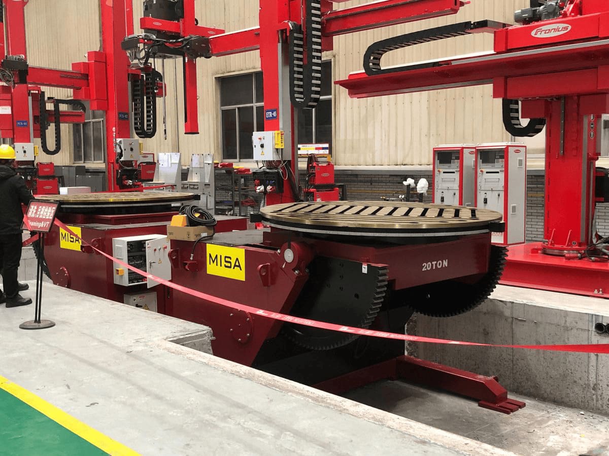
MISA Welding & Cutting Automation manufactures welding positioners, rotators, column-and-boom manipulators and automated welding cells, supplied internationally with spare-parts support. Custom configurations — larger tables, extended tilt, special fixtures, robot interfaces — are developed against the workpiece drawing rather than selected from the catalogue.
10. Frequently asked questions
What is the difference between a welding positioner and a welding rotator?
A positioner grips the workpiece — on a faceplate, in a chuck, or between a headstock and a tailstock — and can rotate and tilt it. A rotator supports a cylindrical workpiece on driven rollers and can only rotate it. The distinction is the drive: a rotator relies on friction between the workpiece outside diameter and its rolls, so it cannot reliably turn irregular or variable-diameter sections. If the workpiece cannot rest stably on its own outside diameter, a rotator is the wrong machine.
How do I size a positioner for an off-centre workpiece?
Work from the offset, not the weight. Calculate the combined mass of workpiece, fixture and chuck, then find how far their combined centre of gravity sits from the rotation axis. That distance is what has to fall inside the machine's rated offset — MISA's MWP-10, MWP-50 and MWP-100 datasheets each state a maximum of 200 mm, separately from a 200 mm maximum centre-of-gravity height, which is a different limit measured along the rotation axis. A workpiece inside the weight rating can still be outside the offset rating.
Do I need two axes or three?
Two axes — rotation and tilt — cover most flat-based work. A third powered lift axis is worth specifying when the working height has to change between jobs, or when a heavy table must be repositioned often. In MISA's range this is the difference between the MEWP series, where the lift is manual and the machine is two-axis, and the MHWP series, where the lift is hydraulic and the machine is three-axis. Confirm the axis count and lift method for the specific model, as these are stated per model.
Is the maximum tilt angle the same as the rated load at that angle?
No, and this catches buyers out. A machine can be specified as tilting to a given angle without being rated for full load at that angle. MISA's MWP-50 series specification lists a tilt range of 0–120°, while the model datasheet quotes 5,000 kg tilting capacity at 90°. Above the angle at which capacity is quoted, assume a reduced rating. Always ask for the rated load at the angle your joint actually requires.
Can a positioner be integrated with a welding robot or a manipulator?
Yes, and it is common in automated cells. What has to be settled at the order stage is the control interface the cell controller can address, the position feedback the cell can synchronise to, and a rotation speed range the torch or robot can follow. These are configuration items, not standard features, so they must be specified with the order rather than assumed.
What maintenance does a welding positioner need?
Lubrication of the tilt gear, rotation drive and slewing bearing on the manufacturer's interval; keeping spatter and cable runs clear of the drives; and checking the tilt locking state as part of the set-up procedure. The single most important habit is ensuring welding current returns through the workpiece or a dedicated collector rather than through the bearings, since current through bearing raceways causes pitting that appears later as premature failure. Confirm the specific service intervals for your model in the supplied documentation.
What certifications do MISA positioners carry?
CE, UKCA, CSA and SGS documentation is offered. Because these apply differently by model and by destination market, the applicable certificates and reports for the machine you are ordering should be confirmed in writing at the enquiry stage rather than assumed to apply uniformly across the range.
Specify from the workpiece, not the catalogue
The fastest route to a correct specification is a workpiece drawing with five figures: total mass including fixture, overall dimensions, centre-of-gravity position, the tilt angle the joint requires, and whether the cell will be manual or automated.
Restored legacy detail
Types of Welding Positioners: Complete Guide
Welding positioners play a critical role in modern manufacturing by precisely holding, rotating, and tilting workpieces to optimize welding operations. They help improve weld quality, enhance safety, and increase overall productivity. Understanding the different types of welding positioners is essential for selecting the right equipment and achieving consistent results in welding processes.
Understanding the Different Types of Welding Positioners
Welding positioners play a critical role in modern manufacturing by precisely holding, rotating, and tilting workpieces to optimize welding operations. They help improve weld quality, enhance safety, and increase overall productivity. Understanding the different types of welding positioners is essential for selecting the right equipment and achieving consistent results in welding processes.
In this article, we will provide a comprehensive guide to various welding positioner types, their features, applications, and selection criteria, helping you make informed decisions for your welding needs.
What Is a Welding Positioner?
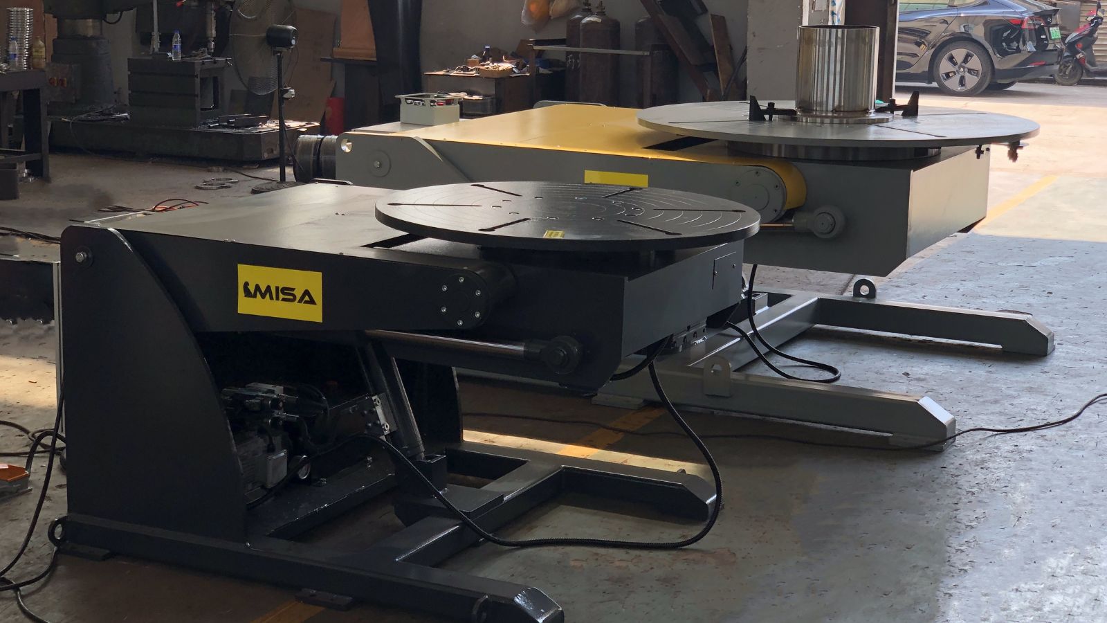
A welding positioner is a mechanical device designed to hold, rotate, and tilt workpieces to provide optimal access for welding. By positioning the workpiece correctly, it allows welders to maintain consistent angles, reduce fatigue, and achieve higher-quality welds.
Welding positioners come in various designs and configurations, offering benefits such as:
- Enhanced precision and repeatability
- Improved safety by reducing manual handling
- Increased productivity and efficiency
- Support for both manual and automated welding processes
Classification of Welding Positioners
Welding positioners can be classified based on several criteria, including movement axes, workpiece type, and control method. Understanding these classifications helps in selecting the right positioner for specific welding applications.
1. By Movement Axes
- 2-Axis Positioners: Allow rotation and tilt of the workpiece, suitable for most standard welding tasks.
- 3-Axis Positioners: Include rotation, tilt, and vertical lift, offering more flexibility for complex welding operations.
2. By Workpiece Type
- Turntable Positioners: Ideal for flat or cylindrical workpieces requiring horizontal rotation.
- Pipe Positioners: Specifically designed for welding pipes and tubular structures.
- Headstock-Tailstock Positioners: Support long shafts, axles, or rods for full-length rotation.
- H-Frame / Ferris Wheel Positioners: Dual-station design for higher throughput in production lines.
3. By Control Method
- Manual Positioners: Hand-operated, low-cost, suitable for small-scale applications.
- Motorized Positioners: Electrically powered with variable speed controls for greater efficiency.
- Hydraulic Positioners: Provide smooth motion and high torque, ideal for heavy or large workpieces.
- Robotic / Automated Positioners: Integrated with welding robots for full automation and high-precision production.
Detailed Types of Welding Positioners
1. By Movement / Mechanism
- 2-Axis Positioner: Rotates and tilts the workpiece, providing basic flexibility for standard welding tasks. Ideal for small to medium-sized components.
- 3-Axis Positioner: Adds vertical lift control to rotation and tilt, allowing more complex welding operations and improved ergonomics for operators.
- Tilt-Rotate Positioner: Combines tilting and rotating functions in a single device with speed control, suitable for repetitive and precise welds.
- Skyhook Positioner: Offers multi-plane rotation, designed for awkward-shaped or asymmetrical workpieces, often used in advanced manufacturing applications.
2. By Workpiece Type / Application
- Turntable Positioner: Features a horizontal rotating table, ideal for flat or cylindrical workpieces. Commonly used in general fabrication and assembly lines.
- Pipe Positioner: Designed specifically for welding pipes and tubular structures. Often includes self-centering clamps and adjustable angles to ensure precise welds.
- Headstock-Tailstock Positioner: Supports long shafts, axles, or rods with rotation along the length of the workpiece, ensuring uniform weld quality.
- H-Frame / Ferris Wheel Positioner: Dual-station design allows one workpiece to be welded while another is being prepared, increasing throughput in high-volume production.
- Roller Bed Positioner: Supports long cylindrical components with continuous rotation, ideal for heavy or elongated workpieces like pipes or beams.
3. By Control / Power
- Manual Positioner: Hand-operated and low-cost, suitable for small-scale workshops or occasional welding tasks.
- Motorized Positioner: Electrically powered with variable speed controls, offering smooth motion and consistent operation for repetitive welding tasks.
- Hydraulic Positioner: Provides high torque and smooth movement, ideal for heavy or oversized workpieces in industrial environments.
- Portable / Mobile Positioner: Lightweight and easy to move, suitable for fieldwork or workshops with limited space.
- Robotic / Automated Positioner: Integrated with robotic welding systems, enabling full automation, high precision, and increased production efficiency.
4. Special and Custom Welding Positioners
- Custom-Built Welding Positioners: Engineered to meet specific project requirements, these positioners are designed for unique workpiece shapes, sizes, or production workflows.
- Ring-Type and Elbow Positioners: Specialized solutions for welding circular, ring-shaped, or elbow components, commonly used in piping and pressure vessel fabrication.
How to Choose the Right Welding Positioner
Selecting the right welding positioner is essential to achieving high-quality welds, maximizing productivity, and ensuring operator safety. The ideal solution depends on several technical and operational factors that should be evaluated before making a purchase.
Workpiece Size, Shape, and Weight
The dimensions and weight of the workpiece are the primary considerations. Positioners must be rated to safely handle the maximum load while maintaining stability during rotation and tilting. Irregular or asymmetrical parts may require multi-axis or custom-built positioners.
Required Movement and Welding Complexity
Simple welding applications may only require a 2-axis positioner, while more complex geometries benefit from 3-axis, skyhook, or robotic positioners. Understanding the required range of motion helps prevent over-specification or underperformance.
Production Volume and Automation Level
For low-volume or manual welding operations, manual or motorized positioners may be sufficient. High-volume production environments often benefit from automated or robotic welding positioners that offer higher consistency and reduced cycle times.
Integration and Workspace Constraints
Consider whether the positioner needs to integrate with robotic welding cells, PLC controls, or existing production lines. Floor space, operator accessibility, and ergonomics should also be evaluated to ensure efficient and safe operation.
Recommended Welding Positioners from MISA
Based on different welding applications and production requirements, MISA offers a wide range of welding positioners designed for precision, durability, and efficiency.
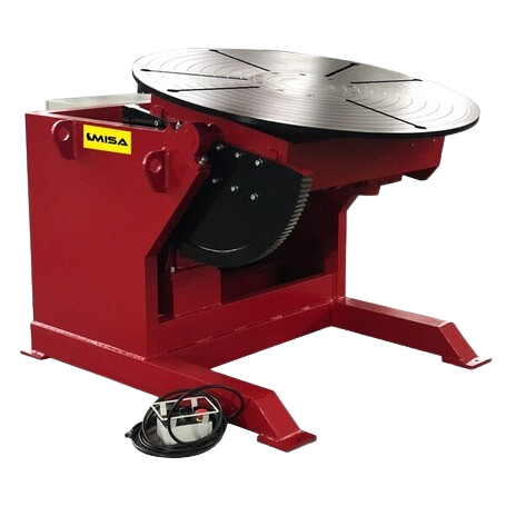
MWP Series Welding Positioner
Ideal for standard welding applications requiring rotation and tilt. Suitable for small to medium-sized workpieces.
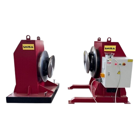
Headstock & Tailstock Positioner
Designed for long and heavy components, offering stable rotation and consistent weld quality.
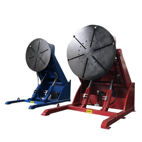
MHWP Series Welding Positioner
Optimized for automated welding lines, providing high precision and seamless robot integration.
Industry Applications of Welding Positioners
Welding positioners are widely used across multiple industries to improve weld quality, enhance productivity, and ensure operator safety. Different industries often require specific types of welding positioners based on workpiece geometry, weight, and production volume.
Automotive Manufacturing
In the automotive industry, welding positioners are commonly used for chassis components, frames, exhaust systems, and subassemblies. Turntable positioners, 2-axis positioners, and robotic welding positioners are widely adopted to support high-volume, repetitive welding tasks while maintaining consistent weld quality.
Heavy Equipment and Construction Machinery
Manufacturers of heavy equipment and construction machinery rely on hydraulic and headstock-tailstock welding positioners to handle large, heavy, and irregular workpieces. These positioners provide high load capacity and stable rotation, enabling precise welding of structural components.
Pipeline and Pressure Vessel Fabrication
Pipe welding positioners, roller bed positioners, and specialized elbow or ring-type positioners are essential in pipeline and pressure vessel fabrication. These systems ensure uniform weld penetration and consistent rotation, reducing the risk of weld defects.
Aerospace and Precision Manufacturing
Aerospace and precision manufacturing applications demand exceptional accuracy and repeatability. Multi-axis welding positioners, including 3-axis and skyhook positioners, are commonly used to weld complex geometries and critical components with tight tolerances.
General Fabrication and Metalworking
In general fabrication workshops, manual and motorized welding positioners are widely used for a broad range of custom and low-to-medium volume projects. Portable welding positioners offer flexibility and efficiency for diverse fabrication needs.
Frequently Asked Questions About Welding Positioners
What are the main types of welding positioners?
The main types of welding positioners include 2-axis positioners, 3-axis positioners, turntable positioners, pipe welding positioners, headstock-tailstock positioners, and robotic welding positioners. Each type is designed to support different workpiece geometries, weights, and production requirements.
What is the difference between a turntable positioner and a 3-axis positioner?
A turntable positioner primarily provides horizontal rotation and is ideal for simple or flat workpieces. A 3-axis welding positioner offers rotation, tilt, and vertical lift, making it suitable for more complex welding applications that require greater flexibility and precision.
How do welding positioners improve weld quality?
Welding positioners allow welders to maintain optimal welding angles and consistent travel speeds. By reducing manual repositioning and operator fatigue, positioners help produce more uniform welds and reduce the likelihood of defects.
Are welding positioners suitable for automated welding systems?
Yes, many welding positioners are designed to integrate seamlessly with robotic welding systems and PLC controls. Robotic welding positioners are commonly used in automated production lines to improve efficiency, repeatability, and throughput.
How do I choose the right welding positioner for my application?
Choosing the right welding positioner depends on factors such as workpiece size, weight, shape, required movement, production volume, and automation needs. Consulting with an experienced manufacturer like MISA can help ensure the optimal solution for your specific application.
Conclusion
Understanding the different types of welding positioners is essential for improving weld quality, enhancing workplace safety, and increasing production efficiency. From basic 2-axis positioners to advanced robotic and custom-built solutions, each type serves a specific purpose based on application requirements.
As an experienced welding positioner manufacturer, MISA provides a comprehensive range of standard and customized welding positioners designed to meet the demands of diverse industries. By selecting the right welding positioner and working with a trusted supplier, manufacturers can achieve consistent, high-quality welding results and long-term operational success.
If you are evaluating welding positioner options for your production line or automation project, MISA’s engineering team is ready to support your needs with expert guidance and tailored solutions.