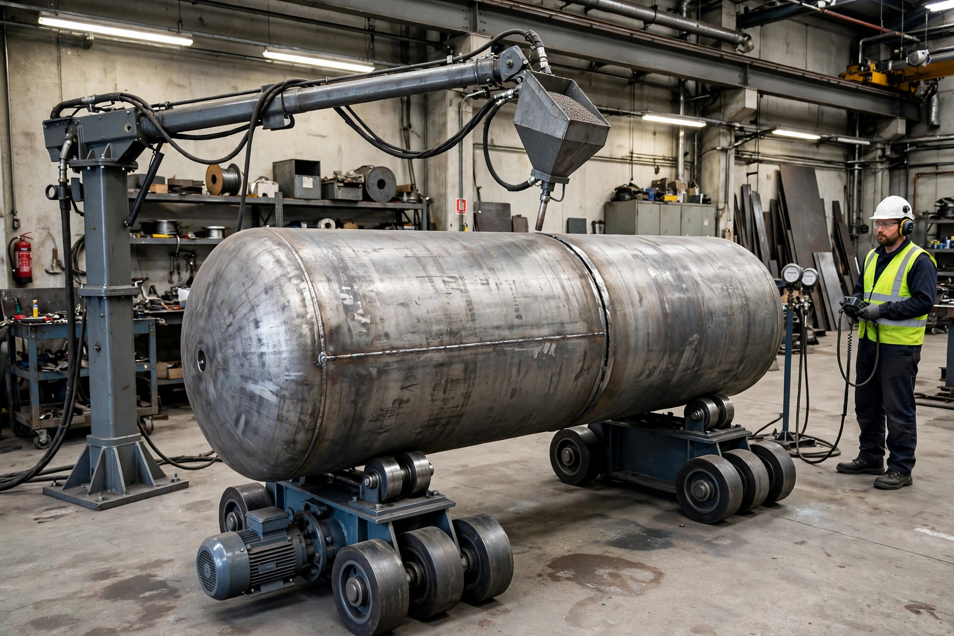
This article is the sequel to What Is a Welding Rotator? — if you need the basics of what a rotator does, start there. This guide assumes you already know, and turns that knowledge into a purchase decision.
The problem with buying on tonnage
A pressure-vessel shop wins more circumferential seam work and manual rotation with a crane is eating the schedule. A supplier quotes a "40-tonne rotator" at an attractive price. It arrives, it lifts the vessel, and halfway through the first heavy shell with a nozzle cluster on one side, the drive stalls on the root pass. The seam drifts, the bead goes irregular, and the job goes back for rework. It was not too small in the catalogue sense. It was sized on the wrong number.
That is the central trap: tonnage is a static, balanced-load rating, and real vessels are rarely static or balanced. A set that safely supports 40 tonnes of centred shell can still be wrong for a 30-tonne vessel whose centre of gravity sits off-axis, whose diameter is at the edge of the wheel spacing, or whose procedure needs a surface speed the drive cannot hold at full load. This guide shows how to size by diameter range, weight, centre-of-gravity eccentricity and torque — not tonnage alone — and ends with the 12 numbers that let any supplier, including MISA, quote the right machine first time.
Short Answer
Buy the rotator that fits your diameter range, your heaviest and most eccentric workpiece, and the surface speeds in your welding procedure — then choose self-aligning or conventional on how often your diameter changes. Send the supplier your diameter range in mm, maximum weight in tonnes including fittings, centre-of-gravity offset in mm, wall thickness and surface condition, weld process and required surface speeds in mm/min, and voltage and facility limits. If a quote arrives without the supplier asking for those numbers, it is a price for a machine, not a solution for your work. For mixed-diameter job shops, a self-aligning set such as the MISA MSAR series is the right starting point; for uniform, heavy, repeat shells, a conventional set such as the MISA MCR series is usually better; for long shells and fit-up work, add powered travel.
Why This Topic Matters
A welding rotator is not a handling accessory. Once in the cell, it sets the weld quality, cycle time, arc-on time, labour and safety of every circumferential seam — and a wrong choice taxes all five, every shift.
Weld quality. A seam is only as good as the travel speed under the torch. If rotation surges or drifts, heat input varies. TWI's SAW guidance is blunt: higher travel speeds reduce bead width and raise porosity, and at the extreme produce undercutting and irregular beads, while too low a speed can cause burn-through. A rotator that cannot hold a steady surface speed creates defects that fail radiography and ultrasonic testing.
Rework. A failed pressure-vessel seam means grinding out, re-welding, re-inspecting and re-documenting, often with the vessel still on the rotator. One rejected seam can cost more hours than the rotator saved in a week.
Cycle time and arc-on time. In manual welding, the arc is off while the vessel is craned and re-tacked. A rotator with a synchronised column-and-boom manipulator keeps the arc on through the full circumference. MISA states that continuous arc operation can improve production efficiency by 30% to 40% — a MISA claim, not an independent measurement.
Labour and crane waiting. Every reposition is a crane lift, a rigger, a welder waiting, and a bay blocked. A powered travel trolley turns shell-to-shell fit-up from a crane job into a controlled drive. In Dallas, 20/40/60-tonne rotators with motorised moving were bought so cylinder sections could be aligned without repeated crane handling.
Safety. A vessel that slips or creeps axially is a dropped-load and crush risk. Remote control keeps the operator clear of the rotating load; stability, end stops and correct wheel loading are safety specifications.
Technical Background
What a rotator set actually is
A welding rotator set (turning rolls) is normally two units: a drive unit and an idler unit. The drive unit rotates the workpiece through friction between its motorised wheels and the vessel surface; the idler supports it. MISA's rotators are friction-driven, with variable-frequency drive (VFD) speed control. The torch stays fixed over the seam while the vessel turns beneath it. That friction drive explains almost every sizing mistake here: torque is transmitted only through wheel-to-shell contact, and anything that reduces it — wrong wheel material or spacing, a shell sitting too high, an eccentric load unloading one wheel set — reduces the torque the drive can deliver, whatever the motor nameplate says.
The three rotator families
Conventional / adjustable rotators (MISA MCR series). Fixed wheel centres, adjusted manually or with a motorised lead screw. Rigid and strong for heavy, uniform work; MISA's record shows sets from 5 tonnes to 1,000 tonnes, including 800- and 1,000-tonne sets for monopiles in Vietnam. Weakness: every diameter change is manual.
Self-aligning rotators (MISA MSAR series). Pivoting wheel brackets swing to match the vessel diameter automatically. In Thailand, sets from 5 tonnes to 200 tonnes covered a range of vessel sizes; in Gemlik, Turkey, 80- and 150-tonne sets served foundation pipe of 4,000–5,000 mm diameter. Strength: changeover speed and even load sharing. Limit: the very heaviest uniform loads.
Fit-up growing lines. A rotator-based line for assembling and welding long pipelines and tower sections can by can — e.g. a 50-tonne line in Rotterdam and 20/40-tonne lines in Brisbane built for 24-hour running. If your work is long multi-can assemblies, price the line, not a single pair.
Speed, stated properly
Rotation speed for welding is a surface speed, in mm/min, not rpm: a 500 mm pipe and a 5,000 mm tower section at the same rpm move past the torch at speeds ten times apart. Typical industry surface speeds are 100–1,200 mm/min (6–60 m/h), with the exact value set by your welding procedure specification (WPS). Check a rotator's range at both ends of your diameter range, at full load, and at the low end where the root pass lives. Low-speed torque under full load is the specification most buyers forget — and the one that stalls a root pass.
The manipulator and the positioner are part of the decision
A rotator rarely works alone. The torch is usually carried by a column-and-boom welding manipulator — MISA's offer vertical strokes of 2–6 m and more, horizontal strokes of 2–8 m and more, SAW, MIG/MAG, TIG and FCAW, twin-wire and narrow-gap heads, and PLC synchronisation. For work that is not a long cylinder — short vessels, dished ends, assemblies that must tilt — the right machine may be a welding positioner (MISA MWP/MEWP/MHWP) instead of, or alongside, a rotator.
Main Comparison / Selection Logic: Size by Four Numbers, Not One
Follow this sequence: diameter range, weight and its distribution, eccentricity and torque, then speed. Tonnage is the last check — it answers "will it hold it?"; the first four determine whether it will weld it. Work through Table 1 with your largest, heaviest, most awkward workpiece, not your average one. Every row can be answered from a drawing and a WPS; if you cannot answer one, send the drawing.
| Sizing criterion | What to send / check | What goes wrong if ignored |
|---|---|---|
| Diameter range (mm) | Smallest/largest outside diameter, in mm; taper or ovality | Small shell loses contact; large shell exceeds wheel spacing |
| Maximum weight (tonnes) | Heaviest workpiece, in tonnes, incl. fittings/internals | Wheel overload, bearing/frame damage |
| Centre of gravity / eccentricity (mm) | CG offset from rotational axis, in mm | One wheel set overloaded 15–25%+; torque spikes; stall/slip |
| Torque and drive | Wheel-load calculation, torque curve at full load; single vs dual drive | Drive stalls at low speed on root pass; slip mid-seam |
| Surface-speed range (mm/min) | WPS travel speeds, in mm/min, at min/max diameter | Heat input drifts; porosity, undercut, burn-through |
| Wall thickness (mm) | Thickness, in mm, material, thin-wall risk | Thin shell dents; oval shell surges |
| Surface condition | Coated, painted, stainless, polished, hot or scaled | Steel wheels mark stainless; PU wheels melt on hot/heavy work |
| Workpiece length (m) | Length, in m; number of rotator sets needed | Shell sags; seam wanders |
| Duty cycle | Shifts/day, hours/week | Intermittent-duty motors overheat on multi-shift work |
| Facility limits | Floor load, flatness, crane capacity, hook height | Machine cannot be installed, or largest shell cannot be loaded |
Buyer conclusion: size for the worst case in every row, and get the supplier's check in writing. The worst case is rarely the same workpiece for every row — your largest diameter may be a light tower section, while your heaviest, most eccentric piece is a short vessel with a manway. Send both drawings, ask for the wheel-load calculation and torque curve at full load, and compare suppliers on those documents.
Trade guidance makes the same point: required torque rises with weight multiplied by centre-of-gravity eccentricity, plus wheel and bearing friction, with a safety factor on top (trade sources commonly cite 1.5 or more). The formula varies by manufacturer, so this article does not publish one as settled engineering. Eccentricity is a torque multiplier acting once per revolution: a vessel that turns smoothly empty can stall at the same position every turn once a heavy nozzle cluster is fitted. Send the offset in mm, and ask the supplier to confirm the drive — single or dual — against it at your lowest welding speed.
Worked Example A — pass time from circumference and surface speed (example, with stated assumptions)
Assume a vessel of 3,000 mm outside diameter, one circumferential SAW pass at 400 mm/min. Circumference = π × 3,000 mm ≈ 9,425 mm. Pass time = 9,425 ÷ 400 ≈ 24 minutes. At 200 mm/min the same seam takes ≈ 47 minutes; at 800 mm/min, ≈ 12 minutes.
Self-Aligning vs Conventional: A Job-Mix Decision
The most common "which type?" question has a short answer: it depends on how often your diameter changes. Both are drive-plus-idler friction rotators with VFD control; the difference is mechanical — self-aligning wheels pivot to follow the shell, conventional wheels sit at a set spacing you adjust — and that drives changeover time, load sharing, rigidity and capacity.
| Factor | Self-aligning (MSAR) | Conventional (MCR) |
|---|---|---|
| Diameter change | Automatic — wheels adapt when the workpiece is placed | Manual bolt/pin or motorised lead-screw adjustment |
| Best for | Mixed diameters, high job mix | Uniform, repeat shells; long runs |
| Changeover time | Minutes | Longer; adjustment and re-checking |
| Load sharing | Even across more wheel contacts; tolerant of ovality | Rigid frame; load at set wheel positions |
| Capacity top end | Medium-heavy (examples to 150 t) | Very heavy (examples to 200 t, 800 t, 1,000 t) |
| Thin-wall shells | Kinder — load spread reduces denting | Needs careful wheel sizing and spacing |
| Setup skill | Low — less room for setup error | Higher — spacing must be set and verified |
| Price, same tonnage | Usually higher | Usually lower |
The buyer conclusion: choose on job mix, and many shops need one of each. If diameters change constantly, a self-aligning set pays for itself in changeover time and avoided setup errors — in Thailand, one customer bought self-aligning sets from 5 tonnes to 200 tonnes to weld different cylinder sizes at the same time. If you run one shell size for months at heavy tonnage, a conventional set's rigidity and lower price win. In Gemlik, even at 80 and 150 tonnes, self-aligning was chosen because pipe diameters reached 4,000–5,000 mm and dual drive plus PU wheels were specified for torque and grip. Decide on how many diameters you run and how often they change, then confirm capacity against Table 1.
Speed Range vs Weld Process
Each process has a travel-speed window set by the WPS, and the rotator must hold a steady surface speed inside it at both ends of your diameter range, under full load, on the slowest pass. SAW is the process most buyers size for: high deposition, deep penetration, mechanised, and largely confined to the flat and horizontal positions — precisely what a rotator provides. The Fabricator's SAW guidance notes deposition up to 100 pounds per hour with multiple electrodes; your WPS will specify a narrower window. Twin-wire and tandem SAW raise deposition but punish speed variation more. MIG/MAG is faster than manual welding but slower than high-deposition SAW; TIG is the slow, precise end; FCAW sits between MIG and SAW.
List, for each process and pass (root, fill, cap), the surface speed in mm/min from the WPS, and check the rotator's VFD range against the slowest and fastest — not a catalogue "100–1,000 mm/min" line measured unloaded. Two checks separate a good speed specification from a catalogue line. First, ask for the torque curve, not the motor kW: a drive that turns freely at high speed may stall at low speed under a 20-tonne eccentric vessel. Second, ask what the speed stability is under load. Trade sources for precision SAW cite about ±1% under full load as the level that keeps heat input consistent; whether your work needs that figure is a question for your WPS and NDT standard, but the question belongs in the RFQ.
Wheel Material vs Surface
Wheels are where capacity becomes physical — a three-way trade between grip, surface protection and heat/load tolerance. MISA offers three options:
- Polyurethane (PU) wheels — delicate or coated surfaces: stainless, painted or polished shells, anywhere marking is a rejection criterion. PU also gives high friction — the Gemlik project specified PU wheels for grip on large-diameter pipe. Limits: heat and very heavy point loads.
- Rubber wheels — general use, a compromise on grip, protection and cost for ordinary carbon-steel work.
- Steel wheels, optionally knurled — heavy carbon-steel sections, hot workpieces, extreme loads where marking does not matter. Steel tolerates heat and load that would destroy PU, but marks finished surfaces and offers lower friction on smooth shells.
Wheel diameter matters too: a larger wheel spreads contact stress, reducing denting risk on thin-wall shells and improving grip on polished surfaces. If your thinnest shell is under 6–8 mm, raise wheel diameter with the supplier explicitly. If shells arrive hot from preheat, say so in the RFQ: wheel material is a temperature decision as much as a load decision.
Application Matrix by Workpiece
Different workpieces need different configurations, not merely different sizes of the same machine. Table 3 maps common work to a starting configuration; treat the figures as example ranges, not MISA catalogue limits. Find your dominant row — the work that pays for the machine — then check that your second-most-common row does not break the choice.
| Workpiece / job | Diameter & weight (examples) | Recommended configuration | Why |
|---|---|---|---|
| Pipe spools | 200–1,200 mm; 0.5–5 t | Small self-aligning set, PU/rubber wheels | Frequent diameter change; small, delicate work |
| Pressure vessels & shells | 1,000–4,000 mm; 5–60 t | Self-aligning or conventional by job mix; dual drive if eccentric | Nozzles create eccentricity |
| Storage tanks, large shells | 2,000–5,000 mm; 20–150 t | Self-aligning (MSAR), dual drive, PU wheels | Large diameter, mixed sizes, grip matters |
| Wind tower sections | 2,000–5,000 mm; 20–200 t | Conventional or fit-up line; powered travel | Long cans, repeat sizes, fit-up dominates |
| Wind monopiles | 4,000–8,000 mm; 100–1,000 t | Heavy conventional sets, multiple units, steel wheels | Extreme weight; rigidity/torque dominate |
| Long pipelines, multi-can | 1,000–5,000 mm; 20–50 t/line | Fit-up growing line + manipulator | Assembly and welding as one line |
| Short / dished vessels | Non-cylindrical or short | Positioner, not a rotator | Rotator needs length and a cylindrical surface |
The buyer conclusion: match the row to your dominant work, then test it against your next two jobs. If the dominant row says self-aligning and the second says heavy conventional, the honest answer may be two sets, or a larger self-aligning set with dual drive. MISA's rotator projects page shows the same logic: Rotterdam bought a line for pipelines, Gemlik bought self-aligning for large mixed-diameter pipe, and Dallas bought conventional with motorised travel for a production line.
Control Package, Voltage and CE
Controls are a safety and productivity decision, cheap relative to the machine — which is why they are so often specified as an afterthought. MISA offers a wired pendant with a 25 ft (about 7.6 m) cable, a wireless pendant with up to 300 ft (about 90 m) range, and a foot switch for tack welding. Ask for the control distance your bay needs, in m, and for a digital speed display so the operator can set surface speed in mm/min.
If the rotator will run with a column-and-boom manipulator, the two must be synchronised — rotation speed matched to welding travel speed — ideally through a PLC interface, as MISA offers. State the interface in the RFQ.
MISA configures electrical systems for 110–600 V, adapted to local safety rules and cable-colour conventions. Send your exact supply voltage in V, your frequency, and the compliance documents your site requires — CE marking and Declaration of Conformity under the Machinery Directive for Europe, and the equivalent elsewhere. MISA's manipulators are CE-marked; confirm the same documentation scope for your rotator package before shipment. Explosion-proof options, including double-layer control cabinets, are available for blasting, painting and chemical environments — say so in the RFQ.
Travel Trolley, Floor and Crane Access
A rotator that cannot be loaded, moved or aligned in your bay is a sculpture. Travel trolley: manual or powered trolleys under the base move vessels along rails and reduce crane dependency; powered travel turns shell-to-shell fit-up from a crane job into a controlled drive. End stops and anti-creep: end-stop rollers prevent axial movement, and anti-creep control keeps the seam under the torch during long multi-pass welds; drift comes from shell taper, bed misalignment or a non-parallel floor. Floor and foundation: rotators need an even, level surface carrying the loaded weight; long lines need rails and a foundation. Send your floor loading limit and ask for the footprint, foundation drawing and installed weight — and confirm the number of rotator sets, since long workpieces need extra pairs to prevent sag. Crane access: confirm crane capacity in tonnes, hook height in m, and bay access for the largest shell.
Cost / ROI / Total Cost Factors
Nobody publishes a meaningful price list for engineered rotators, because the price depends on the 12 numbers in the final table. What can be compared honestly is total cost — purchase price plus the costs the machine creates or removes over its life. The most common error is comparing quotes built on different data: a 20-tonne single-drive set with rubber wheels is not comparable to a 40-tonne dual-drive set with PU wheels, powered travel and PLC synchronisation. Insist every supplier quotes against the same 12 numbers.
| Cost / payback factor | What drives it | How to estimate it |
|---|---|---|
| Purchase price | Capacity, type, drive, wheels, travel, controls | Quote all suppliers against the same 12 numbers |
| Positioning & crane time saved | Seams/week × minutes saved per seam | Time manual positioning per seam; multiply by seams/week |
| Arc-on time gained | Continuous rotation vs stop-start welding | Arc-on share now vs with rotator + manipulator |
| Rework avoided | NDT failure rate; cost per repair | Last 12 months of seam repairs, in hours |
| Labour per seam | Operator hours per seam, including waiting | Operator + rigger hours per seam now |
| Changeover time | Diameter changes/week × minutes per change | Self-aligning vs conventional time, from Table 2 |
| Downtime risk | Duty cycle vs component rating; spares | Duty rating, warranty and spares lead time |
| Installation | Foundation, rails, electrical supply, CE documents | GA drawing and electrical requirements with the quote |
| Consumables & wear | Wheel wear, reducer and motor service | Wheel life and replacement wheel price |
| Floor space & flow | Footprint, travel rails, manipulator envelope | Sketch the cell on your bay plan |
Buyer conclusion: positioning time, crane waiting and rework dominate payback, not the purchase price. A dearer rotator that eliminates a crane lift per seam and halves your repair rate usually pays back faster than the cheapest set.
Worked Example B — payback from seams per week and positioning time saved (example, with stated assumptions)
Assume a shop welds 10 circumferential seams/week, and a rotator with powered travel saves 30 minutes per seam: 10 × 0.5 hours = 5 hours/week, about 250 hours/year. If the loaded welder/rigger/crane cost is, for this example, 80 currency units/hour (state your own rate — an assumption, not a market price), the saving is 5 × 80 = 400/week, about 20,000/year, before rework savings. Set the quoted purchase, installation and commissioning costs against that for the payback period. Use your seam count, minutes saved and hourly rate.
When Not to Use a Welding Rotator
A rotator is the right tool for long, cylindrical workpieces that need circumferential seams. Do not buy one when: the workpiece is not cylindrical — flat plate and boxes cannot be friction-driven; use a welding positioner. It is very short — a short shell cannot sit stably across two wheel sets. It is very small — pipe below roughly 200 mm diameter suits a bench roll or a positioner with a chuck. The centre of gravity is wildly eccentric — an unbalanced load surges once per revolution whatever the drive size; let the supplier say no. The job is longitudinal seams only — that needs the torch to travel along a still shell. The work is one-off — a hired rotator or subcontracted seam may be cheaper. If the workpiece is a cylinder long enough to span two wheel sets and the seam runs around it, a rotator is the tool; otherwise, look at positioners and manipulators first.
Common Buying Mistakes
Each mistake below is one buyers actually make, with its consequence. If any describes your plan, fix it before the RFQ goes out.
- Buying on tonnage alone — an eccentric load overloads one wheel set, the drive stalls or slips mid-seam, and the seam fails NDT and goes back for rework.
- Sizing for the average workpiece, not the largest or most eccentric one — the biggest job cannot run, or runs derated and late; the machine is undersized from day one.
- Ignoring the diameter range — a small shell sits too high and loses contact, while a large shell exceeds the wheel spacing, so neither end welds properly.
- Specifying speed in rpm instead of surface speed in mm/min — travel speed is right at one diameter and wrong at the other, and heat input drifts across the range.
- Choosing a speed range that covers only the welding pass — tacking, inspection and grinding need different speeds, so every seam gains a slow handling step.
- Picking steel wheels for a coated or stainless shell — the surface is marked and the work is rejected; PU wheels on hot or very heavy work melt or crush and slip.
- Skipping the torque curve and buying on motor kW — the drive stalls at low speed under full load on the root pass, the pass that matters most.
- Ordering the rotator without manipulator/positioner synchronisation — two machines cannot run one seam together, and travel speed varies along the seam.
- Forgetting voltage, CE documentation and local electrical standards — delivery is held at commissioning, or the machine cannot legally be put into service.
- No travel trolley or end stops where fit-up needs them — every alignment becomes a crane job, drift pulls the seam off the torch, and fit-up dominates the cycle.
- Ignoring floor, rails and crane access — the rotator cannot be installed where the work is, or the crane cannot load the largest shell.
- Comparing quotes built on different data — the cheapest quote is for a smaller, slower, underequipped machine, and the comparison tells you nothing.
Buyer Checklist
Write each answer down before you contact a supplier. A question you cannot answer is a drawing to send, not a detail to skip.
- What is my smallest and largest diameter, in mm, and my heaviest workpiece, in tonnes, including fittings? — Why: diameter range and worst-case weight set the frame, wheel spacing and drive size.
- Where is the centre of gravity, and how far off-axis can it move, in mm? — Why: eccentricity drives torque and per-wheel load; a centred rating hides it.
- What surface speeds, in mm/min, does my WPS require for each process and pass? — Why: the speed range must cover root, fill and cap at both diameter extremes, under full load.
- What is the shell material, surface finish and wall thickness, in mm? — Why: wheel material and diameter follow surface sensitivity and denting risk.
- How often does my diameter change, and how long can changeover take? — Why: frequent changeover justifies self-aligning; a fixed run does not.
- Do I need dual drive, and has the supplier shown me a torque curve at full load? — Why: kW alone does not prove low-speed torque under an eccentric load.
- Which control do my operators need — wired, wireless, or foot switch — and at what distance, in m? — Why: control distance is a safety and arc-on-time decision.
- Must the rotator synchronise with a manipulator or positioner, and by what interface? — Why: PLC synchronisation makes one continuous seam possible.
- What is my supply voltage, in V, and what CE or local compliance documents must ship with it? — Why: wrong voltage or missing documents stop commissioning.
- Do I need powered travel, end stops, or anti-creep control? — Why: fit-up and axial drift are where seams are lost before welding starts.
- What floor, rail, crane and access limits does my bay impose? — Why: the machine must fit the building, not just the workpiece.
- What duty cycle — shifts per day, hours per week — will it actually run? — Why: intermittent-duty components fail early on 24-hour production, as in the Brisbane project.
What to Send for a Quote: The 12 Numbers
Copy this section into your enquiry. A supplier who receives these 12 numbers can size the frame, wheels, drive and controls; one who receives only "40-tonne rotator, please quote" can only guess — and you will pay for the guess, in price or rework. A range ("800–3,500 mm"), a worst case ("heaviest 42 t") and a drawing beat a single precise-looking number that is wrong. Mark estimates as estimates.
| # | Number / item | Value to send (example) | Why the supplier needs it |
|---|---|---|---|
| 1 | Diameter range | 800–3,500 mm outside diameter | Wheel spacing, frame geometry, contact angle |
| 2 | Workpiece length | 2–12 m; longest shell 6 m | Number of rotator sets, support spacing |
| 3 | Maximum weight | 42 t incl. fittings/internals | Wheel, bearing and frame load |
| 4 | Centre-of-gravity offset | 150 mm off-axis worst case | Torque demand, per-wheel load |
| 5 | Wall thickness & material | 12–40 mm carbon steel; 8 mm stainless | Wheel diameter, denting risk, material |
| 6 | Surface condition | Painted / coated / polished stainless / hot | PU vs rubber vs steel wheels |
| 7 | Weld process & WPS speeds | SAW 300–600 mm/min; TIG root 150 mm/min | VFD speed range, low-speed torque |
| 8 | Seam type & volume | Circumferential; 10 seams/week | Duty cycle, synchronisation, changeover |
| 9 | Rotator type preference | Self-aligning (mixed) or conventional (uniform) | MSAR vs MCR starting point |
| 10 | Control package | Wireless pendant, operator at 10 m; foot switch | Pendant type, range, safety distance |
| 11 | Voltage & compliance | 400 V, 50 Hz; CE Declaration of Conformity | Electrical configuration and documentation |
| 12 | Facility & duty cycle | Crane 50 t, hook 8 m; 2 shifts/day | Footprint, foundation, travel, rating |
Buyer conclusion: a quote built on these 12 numbers can be compared like-for-like, and a quote built on tonnage alone cannot. Send the same table to every supplier, attach the drawing of your heaviest and most eccentric workpiece, and ask each for the same three documents: the wheel-load and torque check, the general-arrangement (GA) layout drawing, and the delivery, installation and commissioning scope with warranty terms.
Final Recommendation
Size by diameter range, weight, centre-of-gravity eccentricity and torque, and send the 12 numbers. Work through Table 1 with your worst-case workpiece; choose self-aligning (MSAR) if diameters change often and conventional (MCR) if they do not; check the speed range in mm/min against your WPS at both diameter extremes and ask for the torque curve at full load; choose wheels for your surface; specify control, voltage and synchronisation now.
MISA's range covers this decision — self-aligning and conventional rotators, fit-up growing lines, manipulators with PLC synchronisation, and positioners for work a rotator cannot hold — and its project record, from a 50-tonne fit-up line in Rotterdam to 80/150-tonne self-aligning sets in Gemlik and 20–200-tonne conventional sets in Dallas, shows those configurations in production. But no project example sizes your workpiece. Only your 12 numbers do that. Send them, ask for the wheel-load and torque check in writing, and buy the machine that passes it.
Next step: copy Table 5 into an enquiry to MISA, attach the drawing of your heaviest and most eccentric workpiece, and request an engineered proposal with a wheel-load/torque check, GA layout and commissioning scope. See also MISA's welding manipulator and welding positioner pages, the rotator project examples, and about MISA.
Sources and further reading
- MISA — Welding Rotator. https://weld-fab.com/welding-rotator/ — Rotator types, wheel options, 110–600 V, pendant options, travel trolley, explosion-proof options, and the MISA 30–40% efficiency claim.
- MISA — Welding Rotator Projects. https://weld-fab.com/welding-rotator-projects/ — Rotterdam 50 t fit-up line; Gemlik 80/150 t self-aligning rotators, 4,000–5,000 mm pipe; Dallas 20–200 t conventional rotators; Brisbane 20/40 t fit-up line, 24-hour running; Vung Tau 100–1,000 t conventional rotators.
- MISA — Welding Manipulator. https://weld-fab.com/welding-manipulator-2/ — Strokes 2–6 m+ vertical, 2–8 m+ horizontal; SAW/MIG/MAG/TIG/FCAW; PLC synchronisation; CE-marked; 110–600 V.
- TWI — What is the effect of travel speed in SA (Submerged Arc) welding? https://www.twi-global.com/technical-knowledge/faqs/faq-what-is-the-effect-of-travel-speed-in-sa-submerged-arc-welding — Travel speed vs bead size, porosity, undercut and burn-through.
- ISO 3834-1:2021 — Quality requirements for fusion welding of metallic materials, Part 1. https://committee.iso.org/standard/81650.html — ISO 3834 series levels (Parts 2–4).
- The Fabricator — 3 ways to boost submerged arc welding performance. https://www.thefabricator.com/thefabricator/article/arcwelding/3-ways-to-boost-submerged-arc-welding-performance — SAW deposition, twin-wire and tandem SAW, travel speeds.
Restored legacy detail
Welding Turning Rolls: Types, Features & Selection
Welding turning rolls are motorized or manually adjustable rotating platforms designed to support and rotate cylindrical workpieces during the welding process. Typically consisting of a drive unit and one or more idler units, these tools are critical in handling heavy, round components such as pipes, pressure vessels, and tanks. Their primary function is to ensure a consistent rotation of the workpiece, allowing welders to perform continuous, uniform welds without constantly repositioning the object.
Welding turning rolls—also known as tank turning rolls or pipe rollers—are essential equipment used for rotating cylindrical workpieces such as tanks, pipes, and vessels during welding. By providing controlled rotation, these systems enhance welding precision, reduce manual handling, and significantly boost operational safety and productivity. Whether you're in fabrication, shipbuilding, or energy sectors, understanding the different types and uses of welding turning rolls can help you optimize your workflow and equipment investment. This guide offers a complete breakdown of their functionality, applications, benefits, top manufacturers, market trends, and how to choose the right model for your needs in 2025.
Table of Contents
- What Are Welding Turning Rolls?
- Types of Welding Turning Rolls
- Working Principle & Benefits of Welding Turning Rolls
- Applications of Welding Turning Rolls
- How to Choose the Right Welding Turning Rolls
- Leading Welding Turning Roll Manufacturers
- Recommended Manufacturer: MISA Welding (Wuxi) Co., Ltd.
- Maintenance & Safety Tips for Welding Turning Rolls
- Cost Considerations & ROI for Welding Turning Rolls
- FAQ – Welding Turning Rolls
- Conclusion
What Are Welding Turning Rolls?
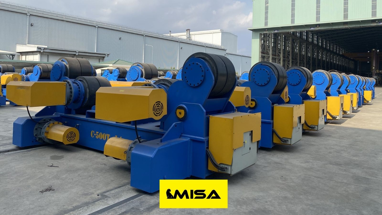
Welding turning rolls are motorized or manually adjustable rotating platforms designed to support and rotate cylindrical workpieces during the welding process. Typically consisting of a drive unit and one or more idler units, these tools are critical in handling heavy, round components such as pipes, pressure vessels, and tanks. Their primary function is to ensure a consistent rotation of the workpiece, allowing welders to perform continuous, uniform welds without constantly repositioning the object.
These systems are especially valuable in industries where precision and efficiency are vital, including petrochemical, shipbuilding, boiler manufacturing, and wind turbine assembly. By minimizing manual intervention, welding turning rolls not only reduce the risk of human error and injury but also significantly increase the throughput of welding operations. They are compatible with a range of welding techniques, including submerged arc welding (SAW), TIG, MIG, and robotic automation systems.
- Drive and Idler Configuration: The drive roll rotates the object using electric or hydraulic motors, while idler rolls support the load and rotate freely.
- Load Capacity: Models vary in their ability to support workpieces from a few thousand pounds to over 180 tons.
- Adjustability: Manual or automatic wheel adjustment allows compatibility with different workpiece diameters.
- Applications: Used in any setting requiring consistent rotation of cylindrical parts for welding or surface treatment.
Types of Welding Turning Rolls
Welding turning rolls come in various configurations to accommodate different sizes, shapes, and materials of workpieces. The right choice depends on the specific production needs, load requirements, and automation level. Below are the main types of turning rolls used in industrial welding settings.
Standard Turning Rolls
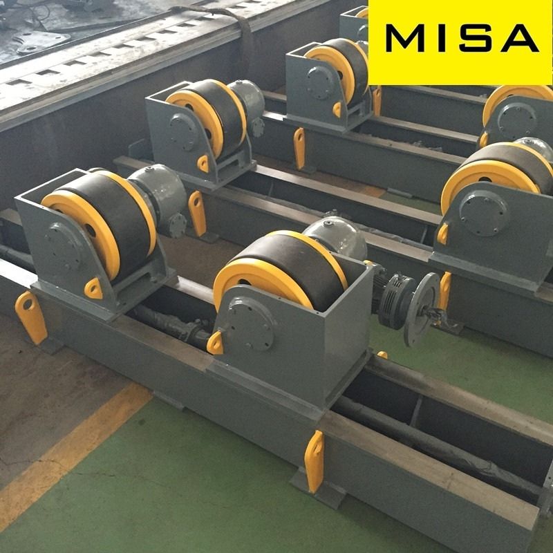
Standard turning rolls are the most commonly used type, equipped with manually adjustable wheels to handle a wide range of cylinder diameters. They are a practical and cost-effective solution for general welding tasks where the workpiece dimensions are relatively stable.
- Manual adjustment: Roll centers can be manually repositioned to accommodate different diameters.
- Cost-effective: Ideal for small-to-medium operations with standard welding requirements.
- Versatile: Suitable for a variety of cylindrical workpieces.
Self-Aligning Turning Rolls
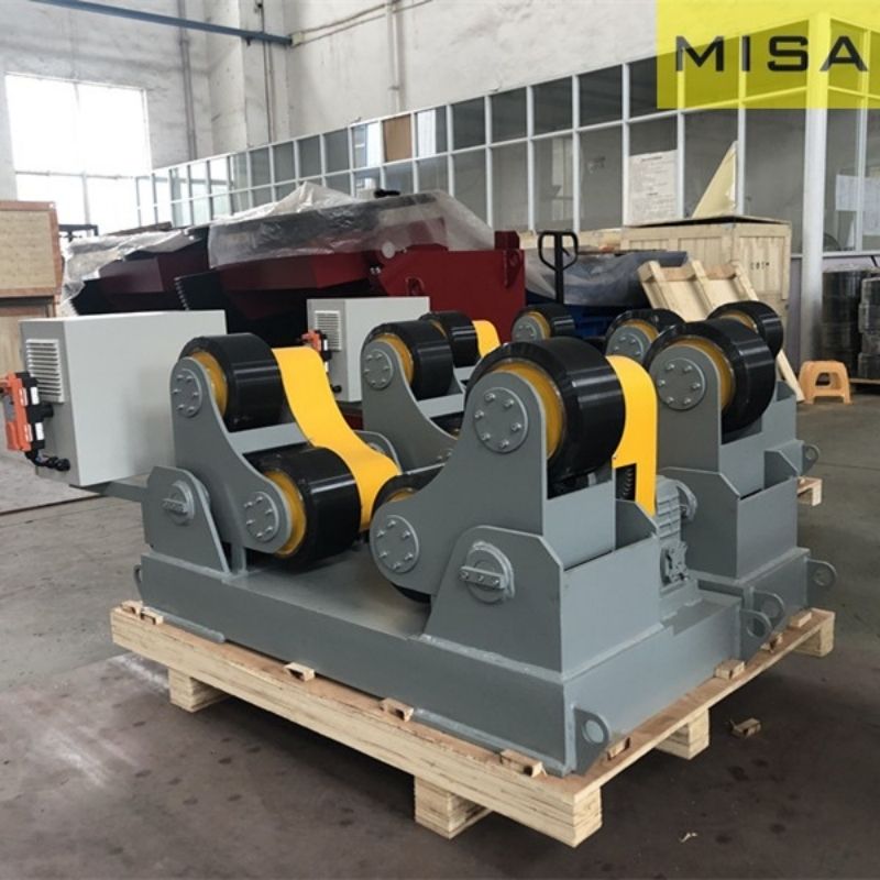
Self-aligning turning rolls automatically adjust to the diameter of the workpiece without requiring manual intervention. This feature makes them highly efficient in operations dealing with varying tank or pipe sizes.
- Automatic adjustment: Wheelsets pivot to match the diameter as the workpiece is loaded.
- Increased safety: Less manual handling reduces injury risk.
- Ideal for batch processing: Perfect for jobs involving frequent workpiece changes.
Constant Centerline & Power Elevation Rolls
These specialized rolls are used when maintaining a fixed welding torch position is critical or when vertical adjustment is necessary to match different fabrication setups.
- Constant centerline rolls: Keep the rotating workpiece centered at a fixed height, perfect for automated or robotic welding.
- Power elevation rolls: Feature vertical lift capabilities, allowing height adjustments for different work environments or weld seam access.
- Precision-friendly: Designed for applications where precise alignment is essential.
Anti-Drift Turning Rolls
Anti-drift rolls are engineered to prevent axial movement or "creep" of the workpiece during rotation. This ensures precise weld seam tracking and is critical in high-accuracy welding jobs.
- Enhanced stability: Keeps the workpiece aligned throughout the process.
- High-precision welding: Minimizes deviation in automated or semi-automated applications.
- Best for large, long workpieces: Especially useful in industries like shipbuilding and aerospace.
| / | Standard Turning Rolls | Self-Aligning Turning Rolls | Anti-Drift Turning Rolls | PLC-Controlled Turning Rolls |
| Adjustment Method | Manual adjustment | Automatic self-aligning | Automatic with axial positioning | Automatic with programmable control |
| Suitable Workpiece Diameter | Fixed or limited range | Wide and variable diameter range | Medium to large diameters requiring high stability | Wide range with high repeatability |
| Load Capacity Range | Low to medium | Medium to heavy | Heavy to extra-heavy | Medium to extra-heavy |
| Rotation Stability | Moderate | High | Very high (prevents axial movement) | Very high (precision controlled) |
| Axial Drift Control | Not included | Limited | Yes (mechanical or hydraulic anti-drift) | Yes (sensor- or logic-based control) |
| Drive System | AC motor with basic reducer | AC motor with flexible drive | Dual-drive or synchronized drive | Servo or inverter-controlled drive |
| Speed Control | Basic variable speed | Variable speed | Precise variable speed | High-precision programmable speed |
| Automation Level | Low | Medium | Medium to high | High |
| Operator Skill Requirement | Higher (manual setup) | Moderate | Moderate | Lower after setup |
| Typical Applications | Small tanks, pipes with consistent sizes | Vessels with varying diameters | Long vessels, pressure vessels, heavy shells | Automated welding lines, robotic welding |
| Best Use Scenario | Cost-sensitive projects with fixed specs | Frequent size changes | High-precision and safety-critical welding | High-volume production and automation |
| Initial Equipment Cost | Low | Medium | Medium to high | High |
| Maintenance Complexity | Low | Low to medium | Medium | Medium to high |
Working Principle & Benefits of Welding Turning Rolls
How Welding Turning Rolls Work
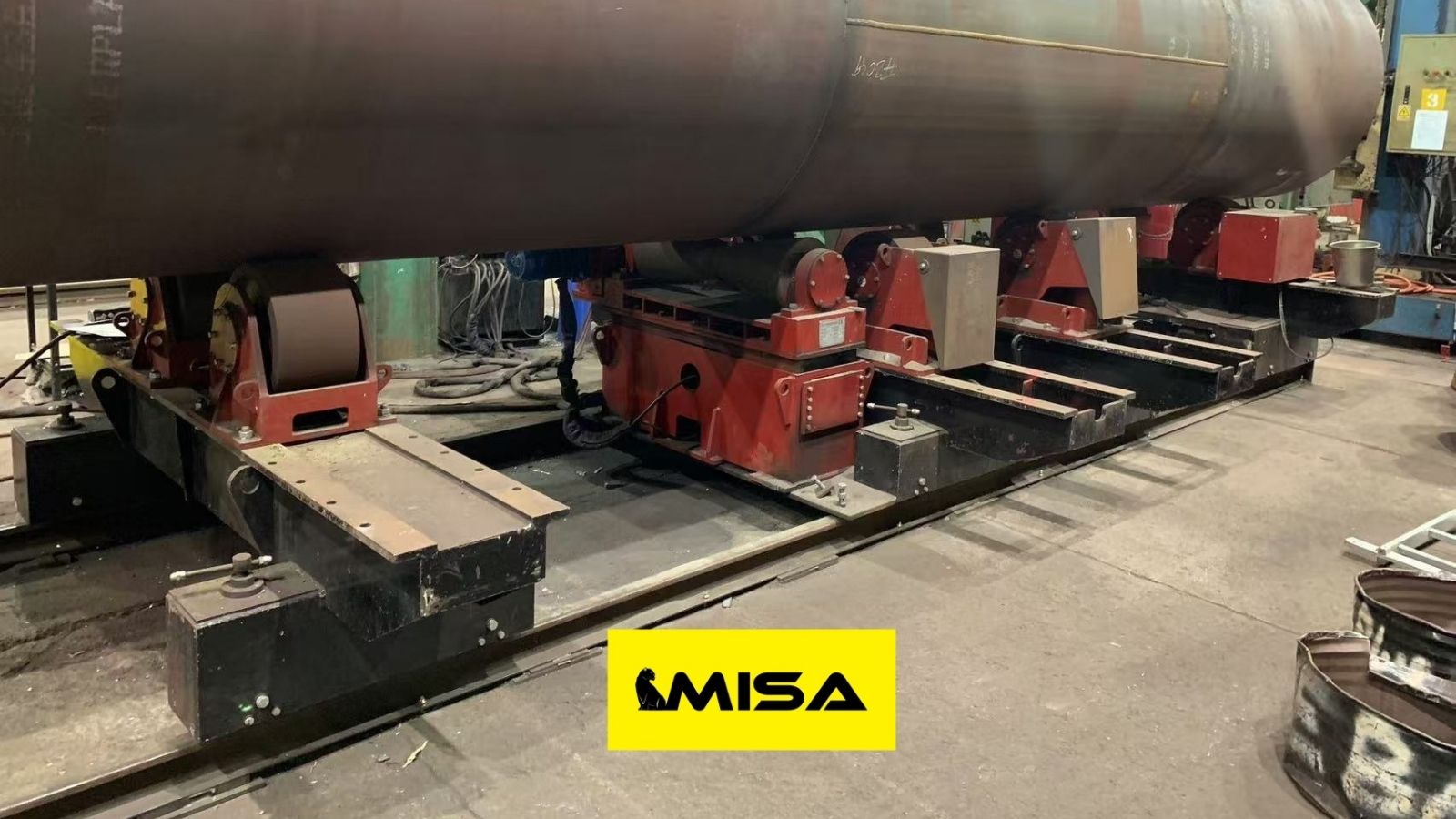
Welding turning rolls operate on a simple yet powerful principle—rotational positioning. A typical setup consists of a drive roll powered by an electric or hydraulic motor and one or more idler rolls that support the load. When a cylindrical workpiece such as a tank or pipe is placed on the rolls, the drive roll initiates controlled rotation. The welder or robotic torch then performs the weld as the object turns, eliminating the need to reposition it manually.
The rotational speed can be adjusted using variable frequency drives (VFDs) to suit different welding processes, such as Submerged Arc Welding (SAW), Tungsten Inert Gas (TIG), or Metal Inert Gas (MIG) welding. This results in a smooth, continuous weld and greater process control.
- Workpiece is loaded onto the rolls.
- Drive roll rotates the workpiece at a controlled speed.
- Welder performs the weld while the object rotates.
- Speed and direction can be adjusted via remote or console controls.
Key Benefits
Integrating welding turning rolls into your production line provides several operational and strategic advantages:
- Consistent Weld Quality: Steady rotation ensures uniform heat distribution and cleaner, stronger welds.
- Increased Productivity: Less repositioning and handling means faster cycle times and reduced labor hours.
- Enhanced Safety: Reduced manual interaction minimizes the risk of injuries and handling accidents.
- Versatile Application: Suitable for various materials, diameters, and weight capacities.
- Cost-Efficiency: Improved throughput and lower labor costs result in a strong return on investment (ROI).
Applications of Welding Turning Rolls
Welding turning rolls are indispensable across various heavy industries where rotating cylindrical components is essential for high-quality, efficient welding. Their ability to support and rotate massive workpieces makes them a go-to solution in sectors requiring precision, productivity, and safety.
Pipeline Manufacturing
In the oil and gas industry, turning rolls are used to weld pipes of varying diameters and lengths. The ability to rotate the pipeline ensures smooth, uninterrupted weld seams and reduces welding errors caused by misalignment or inconsistent rotation.
- Handles long, thick-walled pipes
- Supports MIG, TIG, and SAW welding processes
- Essential for large-diameter pipe fabrication
Tank and Pressure Vessel Fabrication
For the production of boilers, storage tanks, and pressure vessels, turning rolls allow uniform welding around the circumference of the container. This is crucial in industries such as chemical processing and water treatment where structural integrity is non-negotiable.
- Ideal for circular and elliptical vessels
- Supports both internal and external welding
- Ensures consistent weld bead formation
Shipbuilding and Marine Structures
Shipbuilders rely on turning rolls to handle bulky hull sections, ballast tanks, and tubular substructures. These applications demand heavy-duty equipment capable of withstanding marine-grade fabrication loads.
- Facilitates welding of long tubular sections
- Improves accuracy and alignment in modular shipbuilding
- Reduces manpower needed for repositioning
Energy Sector Installations
In both conventional power plants and renewable energy installations, turning rolls are used for components such as steam drums, pressure cylinders, and wind turbine towers. They enable precision welding at a high rate of productivity.
- Accommodates oversized and heavy energy components
- Used in nuclear, thermal, and wind sectors
- Compatible with automated welding lines
General Manufacturing
Any manufacturing environment that involves cylindrical workpieces can benefit from welding turning rolls. This includes HVAC equipment, food-grade tanks, silos, and industrial containers.
- Flexible enough for custom fabrication tasks
- Improves operator safety and reduces fatigue
- Enhances production consistency for small and mid-size firms
How to Choose the Right Welding Turning Rolls
Selecting the ideal welding turning rolls for your operation requires a careful evaluation of technical specifications, operational goals, and safety requirements. Choosing the right model not only optimizes welding performance but also minimizes downtime and enhances workplace safety.
1. Load Capacity
Always match the turning roll’s load rating to the weight of your heaviest workpiece. Load capacities range from 2,000 lbs for small units to over 180 tons for industrial-scale applications.
- Include safety margins to prevent overloading
- Consider dynamic loading during rotation
2. Workpiece Diameter Range
Choose a system that can accommodate the smallest and largest diameters in your product lineup. Self-aligning rolls are better suited for varied diameter ranges, whereas standard rolls require manual adjustment.
- Minimum and maximum diameter range should exceed your needs
- Check for wheel adjustability or automatic alignment features
3. Speed and Control Features
Variable speed control ensures weld consistency and allows adaptation to different welding processes. Look for systems with:
- Inverter-based variable frequency drives (VFDs)
- Remote control panels
- Forward/reverse rotation settings
4. Durability and Material Quality
Welding environments are harsh, with exposure to heat, slag, and vibration. Opt for machines made from high-grade steel or cast iron with protective coatings and sealed bearings.
- Heat-treated rollers and anti-corrosion finishes are ideal
- Heavy-duty construction improves lifespan
5. Safety Features
Safety is non-negotiable in welding operations. Prioritize models with built-in safety mechanisms such as:
- Overload protection systems
- Emergency stop buttons
- Locking wheels or wheel chocks
6. Integration With Automation
If your facility uses robotic welding arms or CNC control systems, ensure the turning rolls can integrate seamlessly through programmable logic controllers (PLCs) or custom automation modules.
7. Budget and ROI
While upfront cost matters, consider the total cost of ownership (TCO), including maintenance, energy usage, and potential productivity gains. A higher initial investment often delivers better long-term ROI.
Leading Welding Turning Roll Manufacturers
When investing in welding turning rolls, choosing a reputable manufacturer ensures product reliability, technical support, and availability of spare parts. Below are some of the most respected names in the industry:
- Ransome – Known for heavy-duty welding equipment and custom automation solutions.
- Koike Aronson – Offers a full line of welding positioners and turning rolls with robust design and controls.
- Pandjiris – Specializes in turning rolls for automated welding and high-precision applications.
- Preston-Eastin – Focuses on heavy fabrication equipment with integrated automation capabilities.
- Profax – Offers cost-effective options for general industrial welding needs.
- LJ Welding – Provides advanced turning rolls with smart controls and modular construction.
- IRCO Automation – Delivers custom-engineered turning rolls tailored to production systems.
- WALDUN – Known for their surface hardening and wear-resistant roll solutions.
- Senlisweld – Offers competitively priced turning rolls with fast global shipping.
- Key Plant Automation – UK-based manufacturer focused on high-tech, PLC-integrated welding systems.
Recommended Manufacturer: MISA Welding (Wuxi) Co., Ltd.
Among the leading manufacturers in the welding equipment industry, MISA Welding (Wuxi) Co., Ltd. stands out as a global innovator and trusted supplier of high-quality welding turning rolls and automation solutions. Established in 1992 and headquartered in Wuxi, China—approximately 180 km from Shanghai (Pudong International Airport / Shanghai Port)—MISA has over three decades of experience delivering cutting-edge welding and positioning equipment to industries worldwide. With a commitment to “quality first, customer supreme, efficiency first, and service supreme,” MISA has built a stellar reputation for reliability, customization, and technical excellence, making it a top choice for businesses seeking advanced welding turning rolls.
Comprehensive Product Portfolio
MISA specializes in designing and manufacturing a diverse range of welding turning rolls, including conventional welding rotators, self-aligning welding rotators, fit-up rotators, and anti-drift rotators, with load capacities ranging from 2 tons to an impressive 2,000 tons and pipe diameter compatibility from 150 mm to 15,000 mm. These rotators are engineered for applications across industries such as automotive, aerospace, shipbuilding, oil and gas, wind energy, pressure vessel manufacturing, and general fabrication. Key features include:
- Customization Options: MISA offers tailored solutions, such as compression-type rotators for specialized workpieces, hydraulic lifts for fit-up growing lines, and adjustable roller spacing (bolt, manual screw, or electric screw adjustments). Customers can also customize colors, logos, and nameplates to align with their branding.
- Advanced Technology: MISA’s rotators incorporate internationally renowned motors, electrical components, and reducers, ensuring durability and precision. Features like variable speed control, remote operation (via wired or wireless pendants), and PLC integration enhance operational efficiency.
- Material Versatility: Turning rolls are available with rubber, steel, or phenolic wheels to suit different workpiece materials and environmental conditions, such as high-temperature or heavy-duty applications.
- Safety and Durability: Equipment is finely polished, painted, and equipped with safety devices like overload protection and clear cable layouts in electric control boxes, ensuring operator safety and long-term reliability.
In addition to welding rotators, MISA’s portfolio includes welding positioners, welding manipulators, CNC cutting machines, H-beam production lines, and auxiliary systems like flux recovery systems, seam trackers, and CCTV monitoring, providing a holistic approach to welding automation.
Global Reach and Industry Expertise
MISA’s global presence is underpinned by over 15 years of export experience, enabling the company to meet diverse international standards, including electrical requirements, voltage, and safety regulations. With CE certifications for all welding positioners and ISO 9001 compliance, MISA ensures its products adhere to rigorous quality and safety benchmarks. The company has collaborated with renowned enterprises across more than 21 countries, serving sectors like oceanic engineering, shipyards, wind turbines, and pressure vessel fabrication, earning trust for its ability to deliver high-performance equipment tailored to specific project needs.
MISA’s state-of-the-art manufacturing facilities in Wuxi, coupled with a professional design team, allow for rapid prototyping and customization. Equipment is trial-operated before delivery to guarantee seamless functionality upon arrival, and some models are delivered as whole units, requiring only power connection for immediate use. For larger systems, MISA provides disassembled delivery with detailed installation support, including on-site commissioning and training within 5–7 working days of customer feedback.
Innovation and R&D Commitment
At the core of MISA’s success is its dedicated research and development (R&D) team, which continuously integrates the latest advancements in welding technology, such as robotic welding, laser welding, and deep penetration TIG (DP-TIG) processes, to enhance product performance. This innovation-driven approach ensures MISA’s turning rolls are future-ready, supporting emerging trends like smart automation and Industry 4.0 integration. For example, MISA’s rotators can be equipped with advanced features like programmable cross slides, seam tracking, and flux recovery systems for submerged arc welding (SAW), optimizing precision and efficiency in complex applications.
Unparalleled Customer Support
MISA prioritizes customer satisfaction through a robust pre-sales and after-sales service framework. The company’s technical team responds to inquiries within 2 hours via email or phone, providing tailored solutions to production challenges. Post-delivery, MISA offers lifelong technical support beyond the standard warranty period, with replacement parts shipped within 48 hours to minimize downtime. Regular maintenance reminders every six months help customers extend equipment lifespan, while proper operation guidelines ensure maximum value. MISA’s customer-centric philosophy is evident in its ability to customize equipment for unique workpieces, such as designing T-slots or special fixtures for irregular shapes, ensuring seamless integration into diverse workflows.
Competitive Advantage in the Market
MISA’s strategic location in China, combined with access to cost-effective raw materials, allows the company to offer premium-quality welding turning rolls at competitive prices, often outperforming Western manufacturers in cost-efficiency without compromising quality. Prices for MISA’s welding rotators typically range from $2,000 to $50,000, depending on load capacity, features, and customization, making them accessible for both small-scale operations and large industrial projects. Unlike some competitors, MISA’s holistic approach—covering design, manufacturing, and after-sales service—ensures a seamless experience, from initial consultation to long-term equipment maintenance.
Why Choose MISA?
Choosing MISA Welding means partnering with a manufacturer that combines engineering excellence, global accessibility, and customer-focused innovation. With a proven track record of delivering reliable, high-performance welding turning rolls, MISA empowers businesses to achieve superior weld quality, enhanced productivity, and operational safety. Whether you need a lightweight rotator for small pipes or a heavy-duty system for wind tower fabrication, MISA’s customizable solutions, backed by industry-leading support, ensure your welding processes are optimized for success. For businesses looking to elevate their welding capabilities in 2025 and beyond, MISA Welding (Wuxi) Co., Ltd. is a strategic partner that delivers unmatched value and performance.
For more information or to request a quote, visit MISA Welding’s official website or contact their sales team directly.
Maintenance & Safety Tips for Welding Turning Rolls
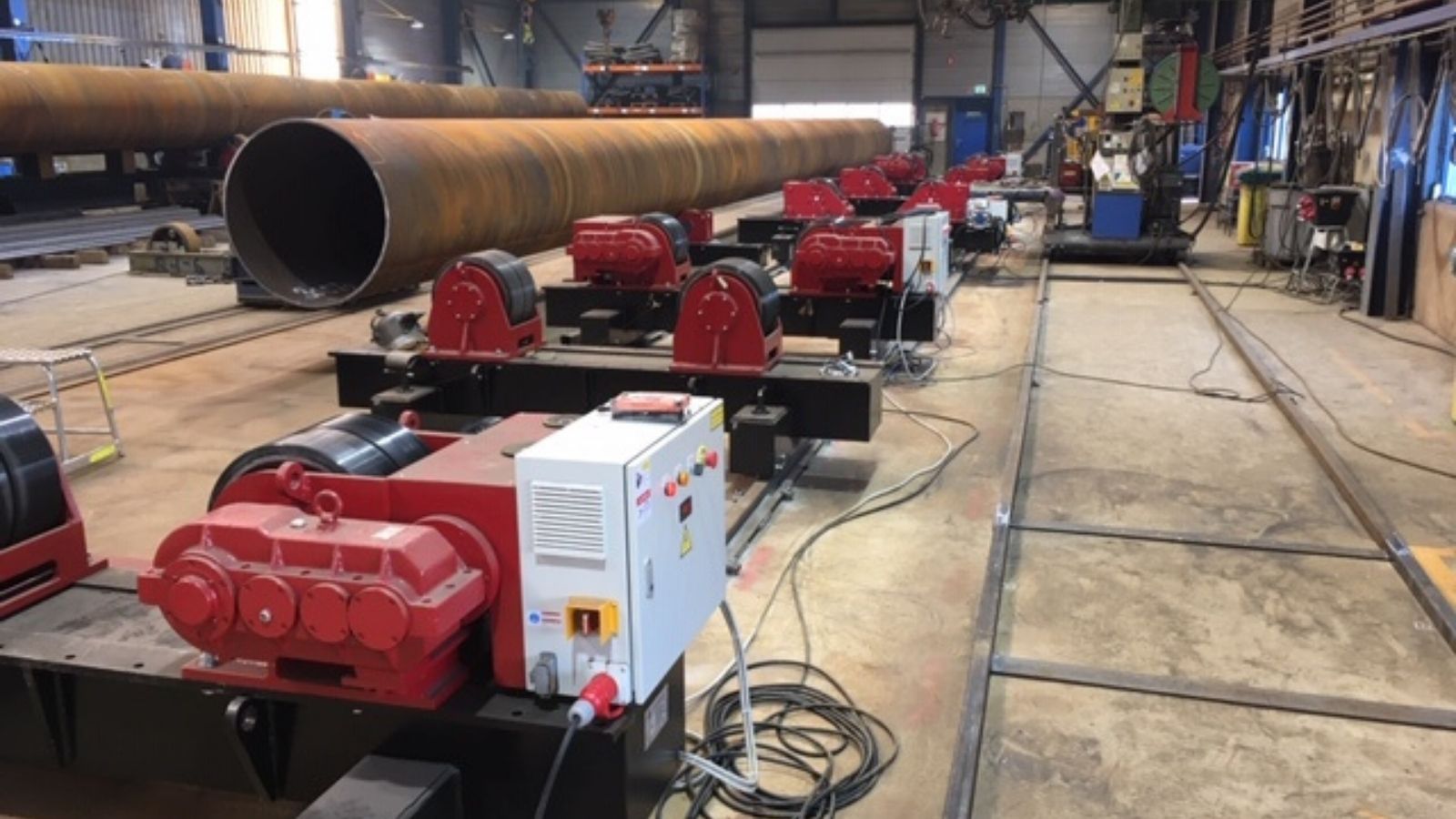
Maintenance Guidelines
Regular maintenance of welding turning rolls ensures optimal performance, minimizes downtime, and extends equipment lifespan. Whether operating in high-volume environments or intermittent production, the following practices are essential:
- Inspect for Wear: Regularly check wheels, bearings, and drive mechanisms for signs of wear or deformation.
- Lubricate Moving Parts: Apply appropriate grease to gears, axles, and rotating components to reduce friction and prevent overheating.
- Check Electrical Systems: Inspect wiring, control panels, and motor connections for fraying, corrosion, or loose terminals.
- Test Control Features: Confirm that emergency stop buttons, variable speed settings, and direction controls function correctly.
- Tighten Bolts and Fasteners: Vibrations can loosen structural components, so periodic tightening is essential.
Safety Best Practices
Ensuring operator safety is paramount in any welding operation. Turning rolls introduce rotational hazards, high temperatures, and heavy loads, making safety training and protocols non-negotiable:
- Secure the Workpiece: Always ensure the cylindrical object is properly centered and secured before activation to prevent slipping or tipping.
- Use PPE: Operators should wear gloves, face shields, fire-resistant clothing, and steel-toe boots.
- Stay Clear of Moving Parts: Never place hands or tools near rotating wheels while in operation.
- Implement Lockout/Tagout (LOTO): During maintenance or setup, isolate the power supply and tag the equipment as “out of service.”
- Keep Work Area Clean: Remove any debris, cables, or obstacles that could pose tripping or fire hazards.
| Maintenance Task | Corresponding Safety Measure |
| Inspect wheels and motor for wear | Ensure workpiece is secured before inspection |
| Lubricate drive components | Lock out electrical power during service |
| Test control panels and emergency stops | Have a trained technician perform diagnostics |
| Tighten bolts and check structural integrity | Wear gloves and use proper hand tools |
| Clean and organize work area | Remove trip hazards and flammable materials |
Cost Considerations & ROI for Welding Turning Rolls
Welding turning rolls are a long-term investment, and understanding their pricing structure and financial impact is crucial for any industrial buyer or procurement team. Costs vary widely depending on capacity, features, materials, and brand reputation. However, the return on investment (ROI) can be substantial when aligned with the right application.
Typical Price Ranges
- Small-scale units (up to 2,000 lbs): $3,000 – $8,000
- Mid-range models (5–20 tons): $10,000 – $30,000
- Heavy-duty systems (50–180 tons): $40,000 – $100,000+
Note: These prices exclude customizations, freight, installation, and warranty packages. Always request detailed quotes from multiple manufacturers for accurate budgeting.
Factors Affecting Cost
- Load capacity: The higher the load rating, the more robust and costly the machine.
- Automation level: PLC integration, self-aligning wheels, and remote controls add to the total cost.
- Build materials: Machines built from hardened steel or equipped with wear-resistant wheels will cost more but last longer.
- Manufacturer origin: Equipment from North America or Europe generally has higher upfront costs than Asian manufacturers.
Maximizing ROI
While the initial investment can seem significant, welding turning rolls often pay for themselves quickly in high-volume operations. Here's how:
- Reduced labor hours: Fewer operators are needed for repositioning and handling.
- Fewer weld defects: Uniform rotation minimizes rework, saving time and materials.
- Higher throughput: Continuous welding enables faster job completion.
- Improved safety: Less manual involvement reduces injury-related costs.
In summary, carefully matching machine specs with your operation's scale and complexity ensures both cost efficiency and high performance. A well-chosen turning roll system will continue delivering value for many years with minimal maintenance and high uptime.
FAQ – Welding Turning Rolls
What are welding turning rolls used for?
Welding turning rolls are used to support, rotate, and position cylindrical workpieces such as tanks, pipes, pressure vessels, and shells during welding, fabrication, or assembly. They allow controlled rotation of the workpiece, improving weld consistency, operator safety, and overall production efficiency.
What is the difference between welding turning rolls and welding rotators?
In most industrial applications, the terms welding turning rolls and welding rotators are used interchangeably. However, “rotators” is sometimes used as a broader term that may include advanced systems such as anti-drift or PLC-controlled turning rolls designed for automated or high-precision welding processes.
How do I determine the correct load capacity for welding turning rolls?
The required load capacity should be based on the maximum weight of the workpiece, including fixtures and accessories. A safety margin—typically 20–30% above the actual load—is recommended to ensure stable operation, reduce mechanical stress, and extend equipment lifespan.
What is axial drift, and why is it a concern when welding?
Axial drift refers to the unintended movement of the workpiece along its longitudinal axis during rotation. This can cause weld misalignment, increased safety risks, and potential damage to equipment. Anti-drift welding turning rolls are designed to prevent this movement, making them ideal for long, heavy, or high-precision welding applications.
When should I choose self-aligning welding turning rolls?
Self-aligning turning rolls are recommended when working with workpieces of varying diameters or when frequent size changes are required. Their automatic adjustment capability reduces setup time and improves operational flexibility, making them suitable for fabrication shops handling diverse projects.
Are PLC-controlled welding turning rolls necessary for automated welding systems?
Yes. PLC-controlled welding turning rolls are typically required for automated or robotic welding systems. They provide precise speed control, synchronization with welding equipment, and repeatable positioning, which are essential for consistent weld quality in high-volume or automated production environments.
What industries commonly use welding turning rolls?
Welding turning rolls are widely used in industries such as pressure vessel manufacturing, oil and gas, wind energy, shipbuilding, steel fabrication, chemical processing, and heavy equipment manufacturing—anywhere large cylindrical components must be welded safely and accurately.
Can welding turning rolls be customized for specific projects?
Yes. Many manufacturers offer customized welding turning rolls to meet specific load capacities, diameter ranges, drive systems, or automation requirements. Custom options may include anti-drift mechanisms, PLC integration, special roller materials, or tailored frame designs.
What maintenance is required for welding turning rolls?
Routine maintenance typically includes checking roller alignment, inspecting drive components, lubricating bearings, and verifying electrical connections. Proper maintenance helps ensure safe operation, consistent rotation, and long-term reliability of the equipment.
How do welding turning rolls improve welding quality and safety?
By providing stable and controlled rotation, welding turning rolls allow welders to maintain optimal welding positions, reduce manual handling, and minimize operator fatigue. This leads to more consistent welds, fewer defects, and improved workplace safety.
Conclusion
Welding turning rolls are indispensable in modern fabrication shops and heavy industries. From their ability to improve weld quality and safety to reducing labor and increasing productivity, these tools deliver significant operational value. Understanding the types, functions, and technical aspects of welding turning rolls empowers buyers to make informed decisions that align with their welding needs and business goals.
Whether you're building pressure vessels, assembling wind turbine components, or simply seeking efficient pipe welding solutions, investing in the right turning rolls can dramatically streamline your workflow. With a wide range of models—standard, self-aligning, constant centerline, and more—tailored to varying workloads and automation levels, there's a solution for every industrial challenge.
We encourage readers to consult with trusted manufacturers, compare features, and consider after-sales support and maintenance plans when choosing equipment. As industries move toward smarter automation, welding turning rolls remain a foundational tool driving consistency, efficiency, and innovation on the shop floor.