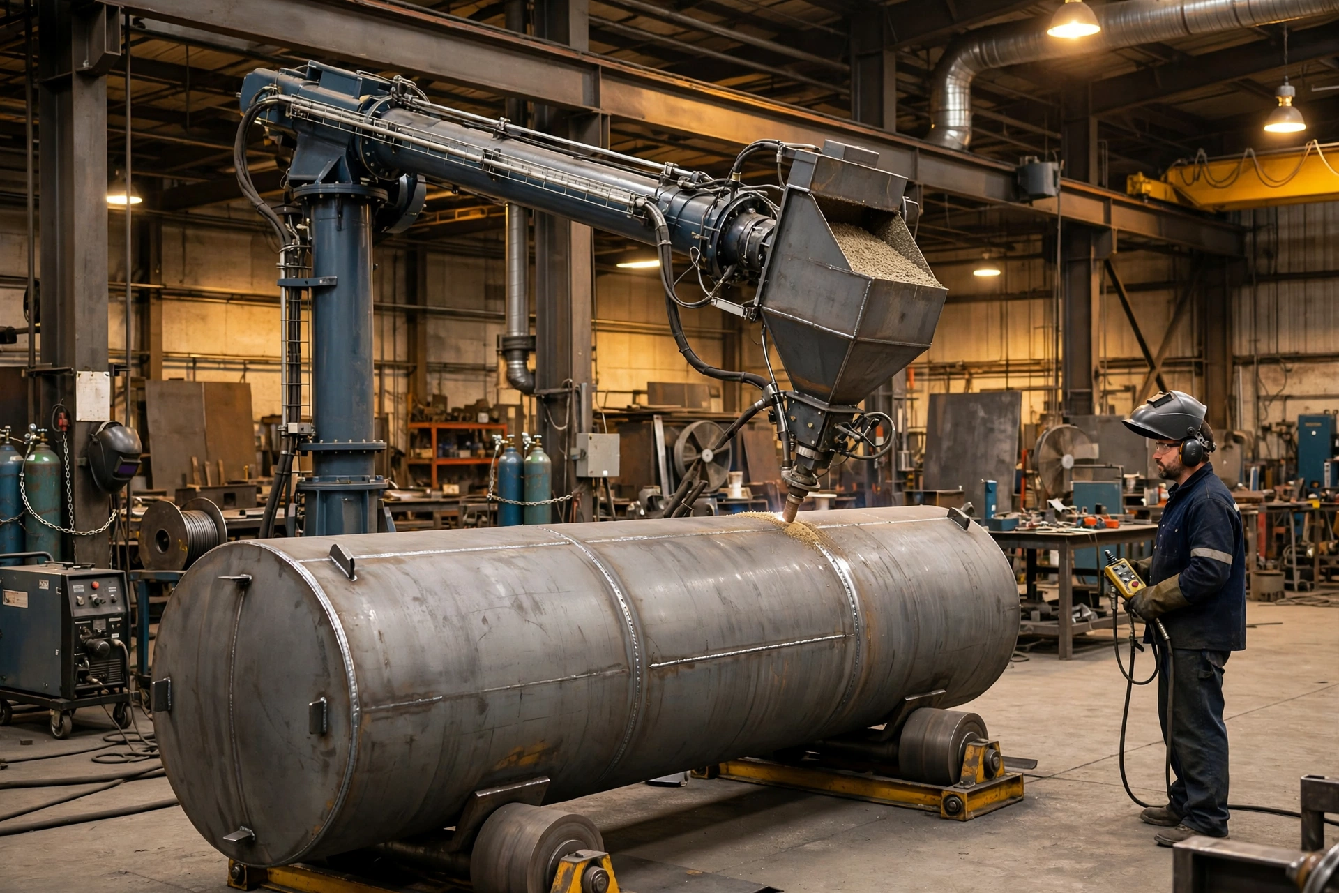
A pressure vessel is on the rotators, the longitudinal seam is 8.0 m long, and the welder is on a ladder with a hand-held torch, trying to hold a steady travel speed and torch angle for the third hour in a row. The bead wanders, the arc length drifts, and the next pass will need the crane again to turn the shell. This is the job a column-and-boom welding manipulator exists to take over — and where buying the wrong one is expensive, because the mistake only shows up when the next, larger vessel arrives and the boom cannot reach it.
A welding manipulator, also called a column-and-boom manipulator, is a machine that moves the welding torch instead of the workpiece. A vertical column lifts the torch, a horizontal boom extends it over or into the workpiece, and a travel base — fixed or motorised on rails — positions the whole machine. Paired with a welding rotator or a welding positioner, it holds the seam in the flat position and drives the torch at a constant, programmable speed while the workpiece turns underneath it.
Short Answer
Buy the manipulator by the seam, not by the catalogue. Size vertical stroke from your largest vessel diameter plus rotator height plus torch clearance; size horizontal reach from your longest longitudinal seam or deepest internal weld plus margin; match the frame and boom-tip payload to the weld process and its flux system; and only then choose fixed versus travelling, and wired versus wireless control. For most pressure-vessel, tank and wind-tower shops, that means a heavy-duty, PLC-synchronised manipulator running submerged arc welding (SAW) with flux recovery, paired with self-aligning rotators — but only if your seams are long, flat-position and thick enough for SAW to earn its keep. If your work is short, thin, out-of-position or one-off, a lighter MIG/MAG or TIG set-up, or a positioner moving the workpiece instead, may be the better spend.
Why This Topic Matters
Weld quality. Manual torch positioning introduces arc-length variation, travel-speed drift and torch-angle error. On a long seam, those errors accumulate into inconsistent penetration and bead profile, which is exactly what non-destructive testing (NDT) finds. A motorised boom and column travel at a programmable, constant speed, holding torch-to-work distance and travel angle steady through the whole joint.
Rework. A repair on a circumferential seam means grinding out, re-welding, re-inspection and a delay to everything behind it in the bay. One rejected seam can cost more than the price difference between a light-duty frame that droops at full reach and a heavy-duty frame that does not.
Cycle time and arc-on time. The Welding Institute (TWI) puts the duty cycle — the share of working time the arc is actually burning — for SAW at 80–95%, against 30–45% for manual MIG/MAG and 25–40% for manual TIG. Mechanised MIG/MAG and TIG reach 80–90%. Those figures exclude set-up time, and TWI itself warns that mechanisation only pays when the whole manufacturing cycle is considered. Even so, the direction is clear: a manipulator keeps the arc burning while a manual set-up spends its time repositioning, changing electrodes and waiting for the crane.
Labour, crane waiting and safety. Every time a heavy shell must be lifted, turned and re-rigged between passes, a crane, a rigger and a welder are all busy doing something that is not welding. A manipulator with a synchronised rotator runs full seam sequences without a crane lift. Welding at height or in confined positions also increases injury risk and degrades quality over a shift; a manipulator lets the operator stand at floor level, watching the weld pool on a camera monitor. MISA's wireless pendant works up to 300 ft (90 m), and its wired pendant reaches 50 ft (15 m).
Technical Background
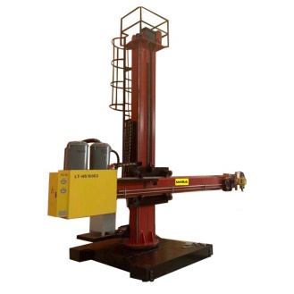
The column provides vertical stroke — the lift that takes the torch to the top of the largest vessel you will weld. MISA's published typical range is 2 m to 6 m+. It is a heavy-gauge welded steel box section, stress-relieved after welding, running on square guide rails or precision linear guides. Column rotation, manual or electric, swings the boom between bays.
The boom provides horizontal stroke — the reach that takes the torch along the seam or into the vessel. MISA's published typical range is 2 m to 8 m+, and some booms are telescopic, extending reach inside a vessel without lengthening the machine. Everything at the tip — torch, cross-slide, flux hopper, wire spool, seam-tracking sensor, camera — is payload the boom must carry without drooping or vibrating.
The cross-slide and rotation head provide fine adjustment. Cross-slide units give fine torch tracking adjustment in the horizontal and vertical axes, so the operator can trim the torch onto the joint without moving the whole boom. The rotation head lets the torch switch rapidly between longitudinal-seam and circumferential-seam orientations.
The torch and welding head are process-specific. A SAW head carries a wire feeder, flux nozzle and recovery hose; a MIG/MAG head carries a gas-shielded torch and feeder; a TIG head is lighter and more precise; a narrow-gap head is a specialist tool for thick sections. The head determines the boom-tip payload, and the payload determines the frame class — which is why process selection comes before frame selection.
The travel base decides whether the machine stays put or moves. A fixed base is anchored to the floor: maximum rigidity, simplest foundation, best for a dedicated, high-volume station. A motorised travelling base runs on rails — standard railway track on MISA machines — so one manipulator can serve a long weldment or move between bays.
The control system ties it together. MISA manipulators are PLC-programmable, with a linkage interface that synchronises the manipulator with a rotator, a positioner or a turntable. Boom travel, column lift and rail travel use AC motors with frequency-converter (VFD) stepless speed regulation, giving constant torque and stable speed at low speed, with digital speed display and preset.
Main Comparison / Selection Logic
The first decision is not stroke. It is type: fixed or travelling, light-duty or heavy-duty. The four types look similar in a photograph and behave very differently in a shop: one is a workshop tool for pipe spools and the other is a production machine for wind towers. The difference is frame rigidity, boom-tip payload, duty cycle and mobility, and each of those is bought once, at order time, and cannot be retrofitted cheaply.
| Manipulator type | Best for | Typical stroke envelope | Tip payload and process | Watch out for |
|---|---|---|---|---|
| Light-duty, fixed | Pipe spools, light tanks, small structural work | Vertical 2–3 m, horizontal 2–3 m | Single MIG/MAG, TIG, light single-wire SAW | Cannot carry a full SAW head with flux recovery; short reach strands larger jobs |
| Light-duty, travelling | Small-to-medium shells across two bays | Vertical 2–3 m, horizontal 2–4 m | MIG/MAG, TIG, light SAW | Rail cost and floor space; limited payload and reach |
| Heavy-duty, fixed | Dedicated line: repeated vessels, tanks, boiler drums | Vertical 4–6 m, horizontal 4–8 m | Full SAW, twin-wire SAW, heavy MIG/MAG, flux recovery, seam tracking | No flexibility if the product mix changes |
| Heavy-duty, travelling | Wind towers, large vessels, shipbuilding, multi-bay shops | Vertical 4–6 m+, horizontal 4–8 m+ | Twin-wire / tandem SAW, narrow-gap, flux recovery, camera monitoring | Highest cost, rails and foundation; verify deflection at full extension |
The buyer conclusion from this comparison is that type follows the seam mix and the shop layout, not the budget line. A fixed light-duty unit is the cheapest way to weld the wrong job: it will weld today's pipe spools beautifully and be unable to touch next year's 4.0 m diameter vessel. Conversely, a heavy-duty travelling machine in a shop that welds one size of tank all day is paying for mobility it never uses. MISA builds all four types — light, heavy-duty, fixed and motorised travelling — so the choice is a specification question, not a supplier limitation. The full range is on the MISA welding manipulator page, and the underlying composition is explained in MISA's technical note on welding manipulators.
How to Size Stroke and Reach
Stroke is not a catalogue number. It is arithmetic, done from your workpiece — and the single most common place where manipulator purchases go wrong.
Vertical stroke is set by the largest vessel you will weld, sitting on its rotators: vessel outside diameter (OD), plus the height the rotator lifts the workpiece centreline, plus torch clearance above the top of the seam, plus safety headroom. Horizontal reach is set by the longest longitudinal seam, or the deepest internal weld — whichever is longer — plus margin to start and finish the seam cleanly. OEM and trade literature commonly suggests roughly 15–20% extra stroke margin beyond current maximum workpiece dimensions for future larger jobs; treat that as a planning rule of thumb, not a MISA specification, and confirm final values with MISA's engineers, who specify every machine per project.
The table below turns that arithmetic into a specification for four common shop profiles. The stroke figures are derived from the stated vessel sizes using the method above.
| Shop profile / workpiece example | Vessel OD | Shell length | Vertical stroke needed | Horizontal reach needed |
|---|---|---|---|---|
| Pipe spool / light tank shop | 1.0 m | 3.0 m | ~2.0 m | ~3.0 m |
| Medium pressure-vessel shop | 2.0 m | 6.0 m | ~3.0 m | ~6.0 m |
| Large pressure-vessel shop | 3.0 m | 8.0 m | ~4.0 m | ~8.0 m |
| Wind tower / heavy vessel shop | 4.0 m+ | 12.0 m+ | 6.0 m+ | 8.0 m+ or travelling base |
The buyer conclusion is blunt: size from the largest job you intend to take in the next five years, plus margin, not from the average job you weld today. Undersizing vertical stroke by 0.5 m means the boom cannot reach the top of the next vessel; undersizing horizontal reach by 1.0 m means the longest seam cannot be finished in one set-up. Either failure is discovered after delivery. All four profiles above sit inside MISA's published typical ranges of 2–6 m+ vertical stroke and 2–8 m+ horizontal stroke; the final stroke is specified per project, not picked off a shelf.
Worked example — sizing a manipulator for a 3.0 m vessel (example, assumptions stated)
Take a stated example: a pressure vessel with an OD of 3.0 m and a shell length of 8.0 m, welded on rotators. Assume the rotator lifts the workpiece centreline 0.6 m above the floor, so the top of the vessel sits 0.6 m + 3.0 m = 3.6 m above the floor. Allow 0.5 m of torch clearance and headroom. Vertical stroke needed is therefore approximately 3.6 m + 0.5 m = 4.1 m, so specify a 4–5 m class column. For the longitudinal seam, horizontal reach must be at least 8.0 m plus start/finish margin — specify an 8.0 m+ boom, or a shorter boom on a travelling base. If the vessel also needs an internal longitudinal seam 8.0 m deep, the boom must reach 8.0 m inside the vessel, which may call for a telescopic boom.
A second worked calculation ties travel speed to deposition rate, using TWI's published SAW figures rather than any supplier claim. TWI reports that a 4.0 mm diameter SAW wire at 700 A and a normal 32 mm stickout deposits approximately 9 kg/h. Suppose — as an example assumption — a 10.0 m longitudinal seam in this vessel needs 20 kg of weld metal (the exact figure depends on joint preparation and plate thickness, and must come from the drawing and welding procedure). At 9 kg/h, arc time is 20 kg ÷ 9 kg/h ≈ 2.2 hours, before set-up, fit-up and inspection. A twin-wire head (+20% deposition, per The Fabricator) would cut that to roughly 1.8 hours; a tandem arrangement, roughly doubling single-wire deposition, to roughly 1.1 hours. These are illustrative figures from published process data, not a production guarantee, but they show why process choice, not just stroke, decides how many vessels a shop finishes per week.
Process Selection: SAW, MIG/MAG, TIG, FCAW
The manipulator is a positioning machine; the weld process is what actually joins the metal. Choosing the process first, and the head second, avoids the most expensive mistake in this whole purchase: a beautifully sized machine carrying the wrong torch.
SAW (submerged arc welding, ISO 4063-121) is the natural partner for a column-and-boom manipulator on long, flat-position seams in thick plate. The arc burns under a blanket of granular flux, so there is no shielding gas, little visible arc, and very high deposition: TWI's equipment guidance puts single-wire current at 200–1,000 A, with a 4.0 mm wire typically run at 600–900 A, and twin-wire systems at 800–1,200 A. Its limits are just as definite: SAW is normally welded in the flat position, because the fluid weld pool and molten slag need gravity to stay in the joint, and flux handling is a system in itself, not an accessory.
MIG/MAG (gas metal arc welding, ISO 4063-131/135) is the flexible all-rounder: good on thinner material, usable out of the flat position, fast to set up. TIG (gas tungsten arc welding, ISO 4063-141) is the precision process — excellent root quality on thin material and stainless steel — at the lowest deposition rate of the four. FCAW (flux-cored arc welding, ISO 4063-136/114) sits between MIG/MAG and SAW: higher deposition than solid-wire MIG/MAG and usable out of position, but with slag to remove and a higher consumable factor than SAW.
The table below compares the four processes on the criteria that decide the manipulator specification, using TWI's published ranges — not MISA performance claims.
| Process (ISO 4063) | Best for | Deposition and duty cycle (TWI ranges) | Limits | Manipulator implication |
|---|---|---|---|---|
| SAW (121) | Long flat seams, thick plate, vessels, wind towers | Deposition ~3–16 kg/h single-wire (TWI); duty cycle 80–95% | Flat position only; flux system required; not for thin material | Heavy-duty frame, flux hopper + recovery, heaviest tip payload |
| MIG/MAG (131/135) | General fabrication, thinner plate, mixed positions | Deposition ~1–15 kg/h (TWI); mechanised duty cycle 80–90% | Shielding gas; lower deposition than SAW on thick joints | Light or medium frame; gas supply to plan |
| TIG (141) | Precision roots, thin material, stainless steel | Lowest deposition of the four; mechanised duty cycle 80–90% | Slow on long thick seams; high skill demand | Light frame; precision cross-slide pays off |
| FCAW (136/114) | Higher-deposition shop work, out-of-position | Deposition ~1–15 kg/h (TWI); mechanised duty cycle 70–85% | Slag removal; consumable factor 1.2 vs 1.02 for SAW | Medium frame; fume extraction to plan |
The buyer conclusion is that SAW wins long flat seams on thick plate and loses everywhere else. If your dominant seam is a 10.0 m longitudinal butt joint in 20 mm plate, SAW on a heavy-duty manipulator is the right answer. If your dominant work is short, thin, positional or one-off, SAW's flux system is dead weight and a MIG/MAG or TIG head on a lighter frame will finish more jobs per week. Pick the process by the joint, then buy the head and the frame that carry it.
Twin-wire, tandem and narrow-gap
Two upgrades deserve a separate decision, because they change both the deposition rate and the boom-tip payload. Twin-wire SAW feeds two smaller-diameter wires through one contact tip from a single power source and feeder; The Fabricator reports it can increase deposition rates by 20% or more without significantly increasing heat input. Tandem SAW uses two wires feeding into the same molten pool, each with its own power source and feeder; The Fabricator reports it roughly doubles the deposition rate of single-wire SAW, and TWI notes the leading wire is normally run on DC positive for penetration while the trailing wire runs on AC to spread the pool. Combining tandem with twin wires gives the highest deposition rates, but also the heaviest head and the largest flux demand — it is a heavy-duty frame decision, not a head swap.
Narrow-gap welding is a different trade: a narrow joint preparation reduces the volume of weld metal, the number of passes and the heat input on thick sections. It is used on thick-wall pressure vessels and nuclear components, where the saving in weld metal and distortion is large. It demands precise torch positioning, a dedicated narrow-gap torch, and seam tracking that can follow the joint — a light frame with a drooping boom will not hold the tolerances narrow-gap needs. Specify narrow-gap only when the joint design and welding procedure call for it; do not buy the head speculatively.
Boom deflection and seam tracking
Deflection is the quiet specification. A boom is a cantilever: the further it extends and the heavier the tip load, the more the tip drops and vibrates. At the torch, a drop of a few millimetres changes arc length, and arc length changes penetration and bead shape. The right question is not "what is the deflection?" but "what is the deflection at full extension, at rated payload, and how is it measured?" Different OEM sources cite different conventions — some quote 1.5 mm per metre of extension, others a ratio such as L/500 or L/1000 — so treat any single figure as a claim to verify, and ask MISA to state the figure for your payload and reach.
Seam tracking is the control-side answer to the same problem. Large shells are never perfectly round or perfectly fitted: ovality, root-gap variation and thermal distortion move the joint while the weld is running. A seam-tracking system — laser or optical sensor ahead of the torch, feeding the cross-slide and, through the PLC, the travel speed and arc voltage — follows the joint instead of assuming it is where the drawing says it is. On long seams, tracking is what keeps the torch in the joint for the whole 8.0 m or 10.0 m. Ask what joint variation the system can follow, in millimetres, and whether it is included in the quoted price.
Flux recovery for SAW
SAW without flux recovery is a manual handling job attached to an automated welding machine. The system has four parts: a hopper, a feed delivering flux ahead of the arc, a vacuum collecting unused flux behind the arc, and a recovery unit — heating cabinet and rotary sieve — that dries and cleans it before it returns to the hopper. TWI puts flux consumption at approximately 1 kg of flux for every 1 kg of deposited weld metal, assuming good housekeeping and an efficient recirculation system. Recycled flux must be separated from slag and fines: slag changes flux composition and therefore weld-metal composition, and fines block feeding. MISA integrates hopper, recovery vacuum, heating cabinet and rotary sieve into the manipulator — but confirm hopper capacity against your longest seam.
Application Matrix
Most shops do not need five manipulator configurations. They need one cell pattern, repeated, that covers most of their work — and the matrix below shows which pattern that is for each common application. A "cell" here means the manipulator plus its partner machine: the rotator or positioner it is synchronised with. A wind tower and a pipe spool are both cylindrical, but one is 4.0 m in diameter and 12.0 m long with a handful of long seams, and the other is 0.5 m in diameter and 3.0 m long with many short seams. The same manipulator cannot serve both well.
| Application | Workpiece | Seam | Recommended cell | Why this cell |
|---|---|---|---|---|
| Pressure vessels | Shells 2.0–4.0 m OD, 6.0–12.0 m long, thick plate | Longitudinal + circumferential, SAW | Heavy-duty manipulator + self-aligning rotators, PLC sync, flux recovery | Long flat seams, high deposition, no crane lifts |
| Wind towers | Tapered sections 3.0–4.0 m+ diameter, long cans | Longitudinal + circumferential, SAW / tandem SAW | Heavy-duty travelling manipulator + rotators | Travelling base for long shells; tandem SAW cuts passes |
| Storage tanks | Large diameter, thinner plate, long seams | Longitudinal + circumferential, SAW / MIG | Heavy-duty or medium manipulator + rotators | Reach matters more than thickness |
| Pipe spools | Small diameter pipe, many short joints | Circumferential, MIG/MAG / TIG | Light-duty manipulator + positioner | Positioner moves the small workpiece; manipulator holds the torch steady |
| Boiler drums | Thick-wall cylinders, internal + external seams | Longitudinal + circumferential, SAW / narrow-gap | Heavy-duty manipulator, telescopic boom + rotators | Internal reach and narrow-gap precision decide it |
| Structural steel / beams | Long straight members, fillet welds | Longitudinal, MIG/MAG / FCAW | Light/medium travelling manipulator | Travelling base follows the beam; process flexibility matters |
The buyer conclusion is that the matrix repeats: pressure vessels, wind towers and tanks all point to the same heavy-duty SAW cell with rotators, while pipe spools and small assemblies point to a light manipulator with a positioner. If most of your revenue sits in one row, buy that row's cell. If revenue is split across two rows, that is the case for a travelling heavy-duty machine with interchangeable heads — say so in the RFQ. MISA's welding positioner range (MWP / MEWP / MHWP) is the partner for smaller, tilt-and-turn work, while the welding rotator range (MCR, MSAR, MSR) is the partner for cylindrical work.
Cost / ROI / Total Cost Factors
Nobody buys a manipulator on machine price alone. The total cost of the cell is the machine, plus the foundation and rails, plus power, plus the welding system, plus flux and consumables, plus training and spares — and the return is measured in arc-on time, rework avoided, crane time saved and delivery dates kept.
The largest return is usually arc-on time: TWI's duty-cycle figures show SAW at 80–95% against 30–45% for manual MIG/MAG. The second return is rework avoided — a constant travel speed and torch-to-work distance produce a consistent bead, and consistent beads pass NDT. The third is crane time, and the fourth is labour: one operator running a synchronised manipulator-and-rotator cell replaces the welder-plus-helper-plus-rigger pattern of manual large-vessel welding.
Against those returns, budget for the full list: the manipulator; the rotator or positioner it synchronises with, if not already on site; rails and foundation for a travelling base; power supply work for the local voltage — MISA machines cover 110–600 V by country, but the transformer, cabling and switchgear are site-specific; the welding power source and head, if not included; the flux recovery system and initial flux stock; seam tracking and camera monitoring, if specified; installation, commissioning and training; and spares such as contact tips, nozzles and pendant cables. A quote that excludes the rails and foundation is not a lower price; it is an incomplete price. Ask MISA for the full cell price, including integration, and for the GA drawings that show the foundation and rail layout — a full engineered proposal typically within 5–7 working days.
When Not to Use a Manipulator
When the workpiece is small and light. A pipe spool, a flange or a small assembly is cheaper and faster to move than the torch is. A positioner that tilts and rotates the workpiece into the flat position, with a fixed or hand-held torch, will finish the job sooner and cost less.
When the work is one-off, short-seam or highly varied. TWI warns that for one-off or small-batch items, the time to prepare and set up a mechanised system can exceed the time to weld manually. If every job is a different size, a different joint and a different process, set-up time eats the arc-on-time gain. A manipulator pays on repetition.
When the seams are short, positional or thin-wall. SAW needs the flat position and thick plate; a manipulator carrying a SAW head cannot rescue a vertical or overhead seam, and it will burn through thin material. Short seams do not give the boom time to earn its keep.
When there is no floor space, no foundation and no rail run. A travelling manipulator needs a straight, level rail run and a foundation that holds it; a heavy-duty fixed unit needs an anchored base. If the bay cannot provide either, the machine cannot be installed as specified.
When the shop has no rotator or positioner to synchronise with, and no plan to buy one. A manipulator without its partner machine is half a cell: it can weld longitudinal seams, but circumferential seams still need the workpiece to turn. Budget the pair, or state in the RFQ that the manipulator must work with an existing rotator — and state its make, model and control interface.
Common Buying Mistakes
- Sizing stroke from the average job, not the largest job. The next larger vessel cannot be welded, and the job is subcontracted at a loss or turned away.
- Forgetting rotator height and torch clearance in vertical stroke. The boom cannot reach the top of the seam, so the vessel must be re-rigged or a taller column retrofitted.
- Specifying reach for the shell length but not internal depth. Internal seams are out of reach, and internal welding reverts to manual work in a confined space.
- Buying a light-duty frame for a heavy SAW head plus flux system. Boom droop and vibration cause arc-length variation, NDT failures, rework and premature wear.
- Treating deflection as a brochure number, not a full-extension, full-payload figure. Torch-to-work distance drifts at full reach, so bead profile and penetration vary along the seam.
- Choosing SAW for out-of-position or thin-wall work. Flux falls away, the weld pool runs, burn-through follows — the process, not the machine, is wrong.
- Ordering the manipulator without the rotator/positioner sync interface. Travel speed is matched by hand, heat input varies, and an extra operator is needed.
- No flux recovery, or an undersized flux system, on a SAW cell. Manual flux handling and stops to refill the hopper destroy the arc-on time the machine was bought to gain.
- Ignoring power supply, voltage and cable runs. The machine arrives and cannot be energised, or a transformer and rewiring delay commissioning by weeks.
- Choosing wireless control without checking range, interference and e-stop integrity. Dropouts mid-weld, or an operator who cannot stop the machine from where they stand.
Buyer Checklist
- What is the largest vessel OD, shell length and weight we will weld in the next 5 years? Stroke and frame size follow the largest job, not today's job.
- How high does the rotator lift the workpiece centreline? Vertical stroke must clear OD plus rotator height plus torch clearance.
- Do we need internal seams, and how deep inside the vessel? Internal reach decides boom length and whether a telescopic boom is needed.
- Which seams dominate — longitudinal, circumferential, or both? This decides the rotation head, column rotation and rotator synchronisation.
- Which weld process (and wire/flux combination) will run most hours? SAW, MIG/MAG, TIG and FCAW need different heads, payloads and duty cycles.
- What is the full boom-tip payload — torch, cross-slide, flux hopper, wire, sensors, operator platform? Payload at full extension drives deflection and frame class.
- What deflection is guaranteed at full extension at rated payload, and how is it measured? A number without load and extension conditions is meaningless.
- Is seam tracking included, and what joint variation can it follow? Ovality and fit-up variation are the norm on large shells.
- How is the manipulator synchronised with our rotator/positioner — PLC, master–slave, or manual? Constant travel speed buys repeatable heat input.
- Fixed base or motorised travelling rail — and what foundation and rail work does each need? Travelling buys flexibility; fixed buys rigidity and a simpler foundation.
- What is our supply voltage, and what transformer and cabling are included? 110–600 V is a range, not a plug-and-play promise.
- Wired or wireless pendant — what is the working radius, and how does the e-stop work? The operator must be able to stop the machine from everywhere they will stand — 50 ft (15 m) wired or 300 ft (90 m) wireless on MISA machines.
What to Send for a Quote
A complete RFQ gets a correct first quote; an incomplete one gets questions. MISA asks for workpiece diameter, length, weight, weld process, required stroke and any existing rotator or positioner on site, and promises an initial technical response within 24 hours and a full engineered proposal with GA drawings typically within 5–7 working days. A supplier can only size a machine from the data it is given; if the data omits the rotator height, the internal depth or the supply voltage, the quote will assume something — and the assumption will be discovered on the shop floor. Ten minutes with a tape measure is cheaper than a retrofit.
| Item to send | Example format | Why MISA needs it |
|---|---|---|
| Workpiece OD and shell length | OD 3.0 m, length 8.0 m | Sets vertical stroke and horizontal reach |
| Workpiece weight | 12,000 kg | Sets rotator capacity and cell loading |
| Largest job in next 5 years | OD 4.0 m, length 10.0 m | Sets stroke margin; avoids undersizing |
| Weld process and joint type | SAW, longitudinal + circumferential butt joints, 20 mm plate | Sets head, flux system and frame class |
| Required stroke | Vertical ~4.1 m, horizontal 8.0 m+ | Confirms the sizing arithmetic above |
| Internal welding needed? | Yes, internal longitudinal seam, 8.0 m deep | Decides boom length / telescopic option |
| Existing rotator / positioner | MSAR self-aligning rotators, 20,000 kg capacity | Sets synchronisation interface |
| Supply voltage | 400 V, 3-phase, 50 Hz | Sets transformer and electrical package |
| Floor space, rails, crane access | Bay 20.0 m × 10.0 m, rail run 12.0 m, crane 10,000 kg | Sets fixed vs travelling and foundation |
| Production target | 4 vessels per month, 2 shifts | Sets duty cycle and shift rating |
| Control preference | Wireless pendant preferred | Sets pendant package and safety review |
The buyer conclusion from this table is simple: if you can fill in every row, you are ready to buy; if three or more rows are blank, you are ready to measure, not to order. Send it once, completely, rather than in three rounds of clarification. More about the company behind the quote is on the MISA about page, and the starting point for any enquiry is the MISA home page.
Final Recommendation
For a pressure-vessel, tank or wind-tower shop welding long seams in thick plate, the recommendation is a heavy-duty column-and-boom manipulator running SAW with flux recovery, PLC-synchronised with self-aligning rotators, specified from the largest vessel on the order book plus margin — vertical stroke from OD plus rotator height plus clearance, horizontal reach from the longest seam or deepest internal weld. Add seam tracking on any seam longer than a few metres, confirm deflection at full extension at rated payload in writing, and choose travelling rails only if the machine must serve more than one bay or a shell longer than the boom. For a pipe-spool or small-assembly shop, the recommendation reverses: a light-duty manipulator with a positioner, running MIG/MAG or TIG, will finish more jobs per week than a heavy SAW cell. Either way, let the proposal — with its GA drawings and stated deflection, payload and synchronisation figures — be the document the decision is made on, not the brochure.
Sources and further reading
- MISA — Welding Manipulator (Column & Boom): https://weld-fab.com/welding-manipulator-2/ — types, typical strokes (vertical 2–6 m+, horizontal 2–8 m+), processes, pendants, voltage, PLC synchronisation, CE marking.
- MISA — Welding Manipulator technical note: https://weld-fab.com/news/welding-and-positioning-equipment-welding-manipulator-welding-column-and-boom/ — composition, rotator/positioner linkage, flux recovery, seam tracking, oscillator.
- TWI — Equipment for Submerged Arc Welding: https://www.twi-global.com/technical-knowledge/job-knowledge/equipment-for-submerged-arc-welding-016 — SAW currents, twin-wire/tandem, stickout vs deposition (4.0 mm wire at 700 A, ~9 kg/h at 32 mm stickout), flux handling.
- TWI — Welding Costs: https://www.twi-global.com/technical-knowledge/job-knowledge/welding-costs-096 — duty cycles by process (SAW 80–95%, mechanised MIG/MAG 80–90%, mechanised TIG 80–90%, mechanised FCAW 70–85%), flux ~1 kg per 1 kg deposited weld metal.
- The Fabricator — Advancements in SAW: https://www.thefabricator.com/thewelder/article/consumables/consumables-corner-advancements-in-saw — twin-wire SAW +20% deposition, tandem SAW roughly doubling single-wire deposition.
- TWI — Welding and Joining Process Classification: https://www.twi-global.com/technical-knowledge/job-knowledge/welding-and-joining-process-classification-001 — ISO 4063 numbers (121 SAW, 131 MIG, 135 MAG, 136 FCAW, 141 TIG).
Restored legacy detail
Column and Boom Welding Manipulator Selection Guide
Target Buyer Evaluation & Technical Selection Guide for B2B Procurement Managers and Welding Engineers
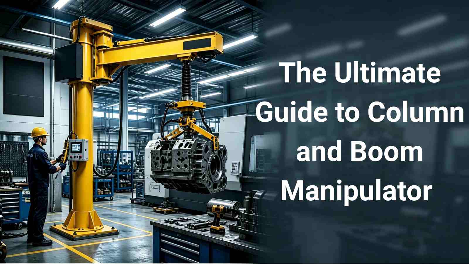
Target Buyer Evaluation & Technical Selection Guide for B2B Procurement Managers and Welding Engineers
Executive Summary for B2B Buyers
In high-capacity industrial fabrication—spanning pressure vessels, wind towers, and heavy piping—manual welding often introduces severe bottlenecks, high labor expenses, and safety risks. A Column and Boom Manipulator (also known as a welding boom and column) automates linear and circumferential welding by precisely positioning and driving the welding head over large workpieces.
This comprehensive guide details structural mechanics, key technical selection parameters, operational ROI, and integration techniques to help plant managers and welding engineers optimize shop-floor yield.
Table of Contents
1. Introduction: Overcoming Heavy Welding Bottlenecks
2. What is a Column and Boom Manipulator & How Does It Work?
3. Key Structural Components: Anatomy of a Welding Manipulator
4. Classification & Types of Manipulators
5. Technical Specifications & Buyer Selection Parameters
6. Application Scenarios & Industry Use Cases
7. Financial ROI & Cost Savings Analysis
8. Why Partner with MISA Manufacturing?
9. Conclusion: Driving Future-Proof Efficiency with Welding Automation
1. Introduction: Overcoming Heavy Welding Bottlenecks
Modern industrial plants face unprecedented pressures: qualified certified welders are increasingly scarce, material specifications demand flawless non-destructive testing (NDT) pass rates, and cycle time directly impacts profit margins. Manual or semi-automated positioning for multi-pass welds on tall structures or long seam pipes yields inconsistent travel speeds, operator fatigue, and excessive downtime.
A Column and Boom Manipulator resolves these operational barriers by transforming a manual process into a continuous, highly controlled machine operation. Engineering leaders such as MISA design automated manipulator systems that seamlessly interface Submerged Arc Welding (SAW), MIG/MAG, and TIG processes with rotators and positioners—delivering up to 40% higher arc-on time and drastic cost reductions.
2. What is a Column and Boom Manipulator & How Does It Work?
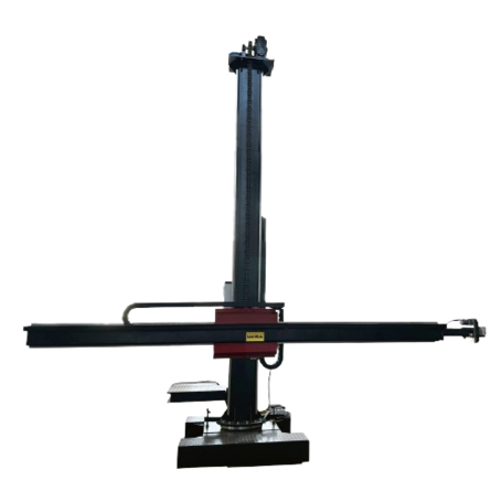
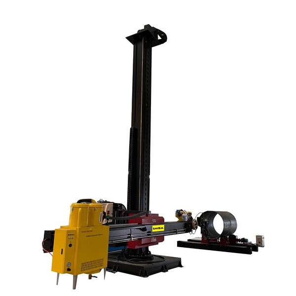
A column and boom manipulator is a structural welding automation unit consisting of a rigid vertical column and a horizontal boom that extends, retracts, and travels vertically along the column. The welding head (along with wire feeders, flux recovery units, and tracking systems) is mounted at the tip of the boom.
Core Operational Logic:
Longitudinal Seam Welding: The workpiece remains stationary while the horizontal boom travels at a precise, controlled welding speed along the seam, or the entire manipulator moves along floor rails.
Circumferential Seam Welding: The boom remains fixed at a specific height and extension, positioning the weld head over the seam while a MISA Welding Rotator or Positioner rotates the cylindrical vessel beneath it.
3. Key Structural Components: Anatomy of a Welding Manipulator
Selecting the right manipulator requires evaluating its mechanical integrity, drive precision, and safety mechanism under heavy dynamic loads.
| Component | Engineering Function | MISA Quality Standard |
| Vertical Column | Provides structural height and stability; guides vertical elevation. | Heavy-duty structural steel box section with high deflection resistance. |
| Horizontal Boom | Reaches inside/outside workpieces to deliver the welding payload. | Machined linear guide rails ensuring vibration-free horizontal stroke. |
| Elevating Mechanism | Drives boom up/down; includes counterweights and brake systems. | Fitted with anti-fall safety locking gear and heavy-duty chain drive. |
| Slewing Structure | Rotates the entire column assembly (manual or motorized 360°). | Precision slewing bearing with smooth locking mechanism. |
| Motorized Travel Base | Carries the manipulator along shop-floor tracks for long vessels. | VFD-driven AC motors with rail clamps for accurate positioning. |
| Cross-Slide & Tracker | Fine-tunes torch alignment along X/Y axes during welding. | Motorized cross-slides with tactile or laser seam tracking compatibility. |
4. Classification & Types of Manipulators
Depending on workpiece dimensions and workshop throughput, B2B buyers can choose across several structural categories:
Light-Duty Type (Stroke: 1.5m × 1.5m to 3m × 3m)
Ideal for smaller diameter pipe spooling, light tank fabrication, and MIG/TIG processes. Lightweight structure with fast setup times.
Heavy-Duty Type (Stroke: 4m × 4m up to 8m × 8m+)
Engineered for Submerged Arc Welding (SAW) with heavy dual-wire payloads, flux recovery systems, and heavy operator platforms. Designed for thick-walled pressure vessels and wind towers.
Fixed-Base vs. Motorized Moving Type
- Fixed-Base manipulators are anchored directly to the shop floor, ideal for dedicated work bays.
- Motorized Moving types mount onto floor-level rail cars, allowing a single manipulator to service multiple welding stations across the plant floor.
5. Technical Specifications & Buyer Selection Parameters
When evaluating suppliers, purchasing managers and welding engineers should perform calculations based on their maximum workpiece specs:
Key Selection Checklist for Procurement & Engineering:
- Maximum Vertical Reach (H): Must clear the maximum outer diameter (OD) of vessels placed on turning rolls.
- Effective Horizontal Stroke (L): Must span the entire length of the weld seam or internal reach depth.
- Boom End Load Capacity: Must account for torch weight, cross-slide assembly, flux hopper, wire spool, and seam tracking sensors.
- Deflection Tolerance: High-end manipulators maintain deflection under δ ≤ 1.5 mm/m at full extension.
6. Application Scenarios & Industry Use Cases
- Pressure Vessels & Boilers (ASME Section VIII): Achieves defect-free, 100% X-ray compliant multi-pass SAW welds on thick steel plates.
- Wind Energy Towers & Monopiles: Handles large-diameter circumferential joints when synchronized with high-tonnage fit-up rotators.
- Petrochemical Pipe Spooling: Automates root pass and cap welds on high-alloy steel pipes, ensuring consistent penetration.
7. Financial ROI & Cost Savings Analysis
Investing in automated manipulators shifts shop performance from manual dependency to capital efficiency:
- Labor Expense Reduction: A single operator can oversee a fully automated column and boom welding cell, reducing direct manual welder headcounts by 50–70%.
- Elimination of Rework: Steady automated travel speed prevents burn-through, lack of fusion, and porosity, driving NDT pass rates close to 99%.
- Calculated Payback Period: Average payback is achieved within 10 to 14 months based on double-shift shop operations.
8. Why Partner with MISA Manufacturing?
As a specialized global manufacturer of welding automation equipment, MISA brings engineering expertise, customized solutions, and robust build quality to industrial plants worldwide.
- Comprehensive Product Range: From light-duty manipulators to customized heavy-duty rail-moving installations.
- Turnkey Welding Cells: Full integration of MISA Column & Boom Manipulators with MISA Turning Rolls (MCR, MSAR series) and Welding Positioners (MWP series) under a single intuitive master controller.
- Strict Quality Control: ISO-compliant manufacturing, international standard electrical components (Schneider/Siemens), and rigorous factory load testing prior to shipment.
- Global Support & Customization: Tailored boom lengths, payload capacities, and specialized welding process integration (SAW tandem wire, narrow gap, TIG hot wire).
9. Conclusion: Driving Future-Proof Efficiency with Welding Automation
In an increasingly competitive industrial landscape, upgrading to automated welding technology is no longer optional—it is a vital imperative for long-term growth. The Column and Boom Manipulator (2026 Edition) stands as an indispensable asset for heavy manufacturing, bridging the gap between stringent weld quality standards and the growing shortage of skilled manual labor. By offering pinpoint positional precision, high boom deflection stability, and seamless synchronization with turning rolls and positioners, a column and boom system transforms demanding fabrication challenges into streamlined, highly repeatable operations.
When evaluating your automation investment, success hinges on choosing an engineering partner capable of tailoring machinery to your precise workpiece dimensions, duty cycles, and shop floor layouts. MISA continues to empower plant managers, procurement teams, and welding engineers across the globe with robust, ISO-compliant equipment engineered for reliability, high NDT pass rates, and fast capital payback. Equipping your facility with MISA’s column and boom manipulators ensures that your operations remain scalable, safe, and cost-effective for years to come.
Restored legacy detail
How to Choose a Column and Boom Welding Machine
You can explore MISA’s full product line and request a custom quote directly on their official website: https://www.misamfg.com/ .
Introduction: Why Column Boom Welding Machines Matter More Than Ever in 2026
Table of contents
- The Core Role of Column & Boom Manipulators
- Equipment Classification & Production Fit
- Technical Specs That Dictate Real Floor Performance
- 2026 Tech Trends Redefining Your Investment
- Practical Evaluation: Grounding Specs in Factory Reality
- The Real Mathematics of ROI: Moving Beyond the Initial Price Tag
- Strategic Sourcing: Why Engineering Support Trumps a Cheap Quote
- A Practical Comparison of Common Column Boom Welding Machine Types
- Conclusion
- Frequently Asked Questions (FAQ)
The Core Role of Column & Boom Manipulators
Equipment Classification & Production Fit
Technical Specs That Dictate Real Floor Performance
2026 Tech Trends Redefining Your Investment
- Intelligent Seam Tracking: Large workpieces suffer from fit-up deviations and thermal distortion. Modern tracking—via arc voltage or advanced sensors—automatically compensates for these variances, eliminating reliance on an operator’s manual corrections.
- Digital Diagnostics & Remote Support: Smart control panels with real-time parameter logging and remote troubleshooting are no longer premium luxuries; they are essential for minimizing downtime, especially in global supply chains.
- Refined Motion Control: Upgraded inverter drives and energy-efficient motors ensure microscopic precision and zero stutter during extended boom travel, translating directly to flawless weld beads.
- Ergonomics & Safety: Shift the operator away from toxic fume zones and awkward positioning. Modern setups focus on human-machine collaboration, allowing skilled welders to supervise the arc safely from a centralized console.
Practical Evaluation: Grounding Specs in Factory Reality
The Real Mathematics of ROI: Moving Beyond the Initial Price Tag
- Defect Eradication and Consistent Consistency: The real cash drain in heavy fabrication isn't just the hourly welder wage—it’s the brutal cost of gouging, re-welding, and re-testing defective joints caused by human fatigue. A manipulator locks in perfect torch geometry and travel speed over long, multi-meter passes, driving rework rates down toward zero.
- Maximizing "Arc-On" Time: Manual welding on massive cylindrical vessels is plagued by hidden inefficiencies—constant scaffolding adjustments, operator repositioning, and awkward breaks. An automated manipulator converts this fragmented chaos into continuous, predictable throughput, drastically increasing daily arc-on time and insulating you from late-delivery penalties.
- The Hidden Trap of Unscheduled Downtime: A budget-friendly machine that saves you $15,000 upfront but suffers from a fried generic inverter or a loose guide rail three months later is a financial liability. Lost production days, missed shipping windows, and the headache of sourcing obscure parts will instantly wipe out any initial purchase discount.
Strategic Sourcing: Why Engineering Support Trumps a Cheap Quote
- Deep Customization Capabilities: Heavy fabrication rarely tolerates off-the-shelf specs. True manufacturers can seamlessly modify column heights, boom extensions, or specialized integration interfaces to match your specific workshop geometry and process requirements without compromising structural rigidity.
- True Export and Compliance Readiness: Sourcing globally requires rigorous adherence to destination electrical codes, robust seawater-resistant packaging, crystal-clear schematic drawings, and comprehensive factory acceptance testing (FAT). If a supplier cuts corners here, your cheap machine will sit stranded in customs or red-tagged on your floor.
- Ecosystem Symbiosis: A standalone manipulator is just a heavy piece of steel. It must function as a synchronized cell.
A Practical Comparison of Common Column Boom Welding Machine Types
| Machine Type | Core Profile & Processes | Best Fit & Operation |
| Light-Duty Fixed | Standard column with a short boom; lower load capacity; primarily optimized for basic/semi-automatic TIG and MIG welding. | Best for small-bore piping, standard tank fabrication, and lower-volume general machine shops. |
| Heavy-Duty Fixed | Extended column and long boom travel; maximum structural rigidity; perfectly matched for high-current SAW and heavy cladding. | Engineered for thick-walled pressure vessels, massive cylinders, and high-duty, continuous industrial welding. |
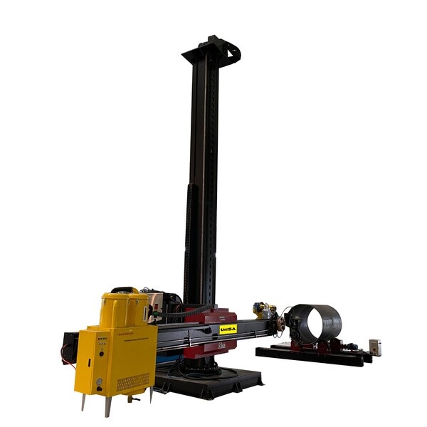
| Motorized Traveling | Mounted on floor rails for cross-shop mobility; medium-to-high load capacity; fully compatible with automatic SAW, MIG, and TIG. |
Ideal for large-scale workshops handling massive workpieces across multiple bays, maximizing floor layout flexibility.
|
| Buying Logic | Critical focus must be placed on deflection control and vibration resistance at full boom extension, not just nominal catalog numbers. | Avoid over-specifying. Let MISA’s application team run the floor math upfront to avoid wasting budget on unused features. |
Conclusion
Frequently Asked Questions (FAQ)
What is the difference between a Column Boom Welding Machine and a welding manipulator?
Which welding processes can be used with a Column Boom Welding Machine?
How do I choose between a fixed type and a motorized traveling type?
Is a Column Boom Welding Machine worth the investment for medium-sized factories?
Why do buyers choose MISA for welding automation equipment?
Where can I learn more or get a quotation?
You can explore MISA’s full product line and request a custom quote directly on their official website: https://www.misamfg.com/.
Restored legacy detail
Welding Manipulator Column and Boom Technical Guide
In today's competitive fabrication landscape, consistency, repeatability, and throughput define the difference between a profitable workshop and one that struggles to meet delivery schedules. A welding manipulator column and boom is among the most productive investments a fabricator can make — enabling precise torch positioning over large or complex workpieces while dramatically reducing operator fatigue and rework rates.
In today's competitive fabrication landscape, consistency, repeatability, and throughput define the difference between a profitable workshop and one that struggles to meet delivery schedules. A welding manipulator column and boom is among the most productive investments a fabricator can make — enabling precise torch positioning over large or complex workpieces while dramatically reducing operator fatigue and rework rates.
Whether you are fabricating pressure vessels to ASME Section VIII requirements, welding wind tower sections up to 30 metres in length, or running high-deposition submerged arc weld (SAW) passes on large pipe spools, a column-and-boom manipulator is the industry-standard solution for torch positioning in automated and semi-automated welding cells.
This guide has been written for engineers, procurement managers, and welding coordinators — drawing on the practices and product philosophies of leading global suppliers such as Keyplant (Sweden), Red-D-Arc (North America), LJ Welding Automation (Canada), IRCO Automation (USA), and Redrock Automation.
Related Search Terms
1. What Is a Welding Manipulator Column and Boom?
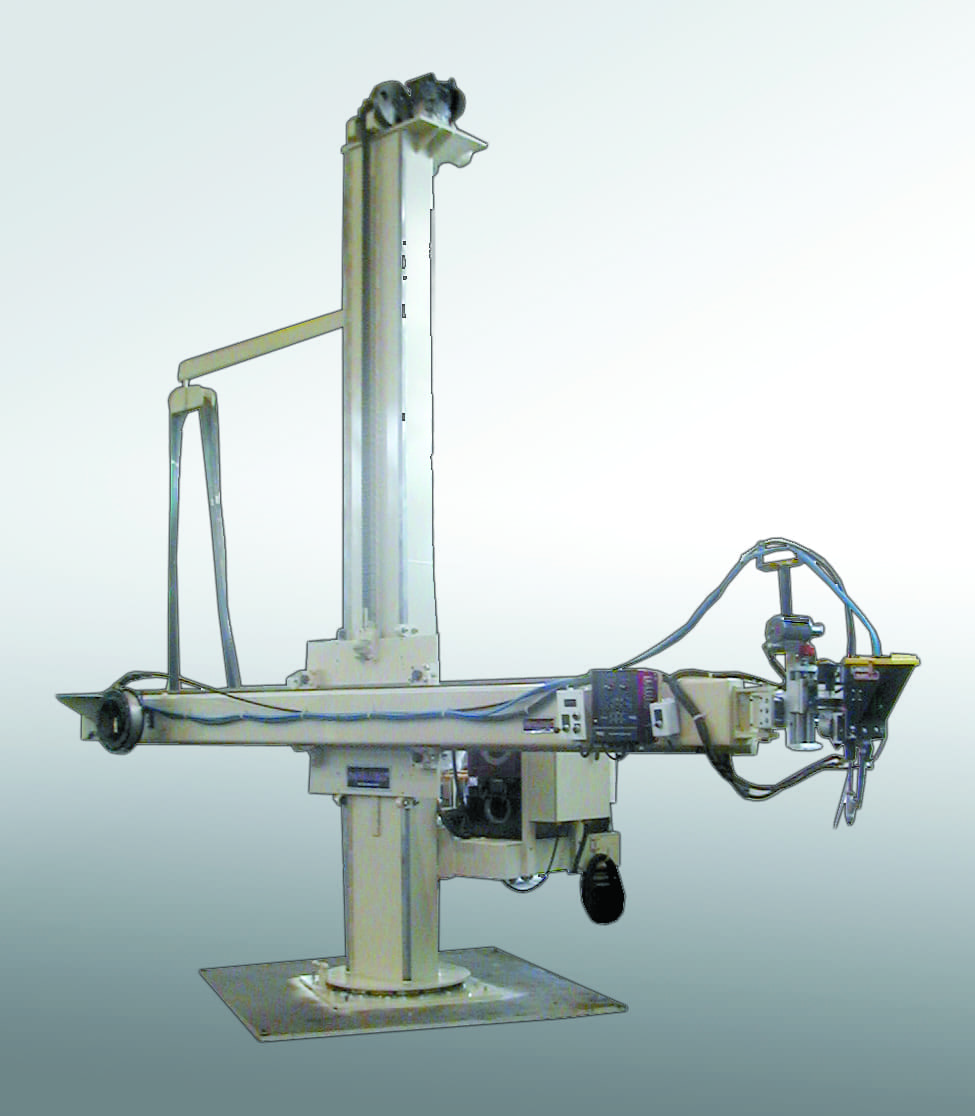
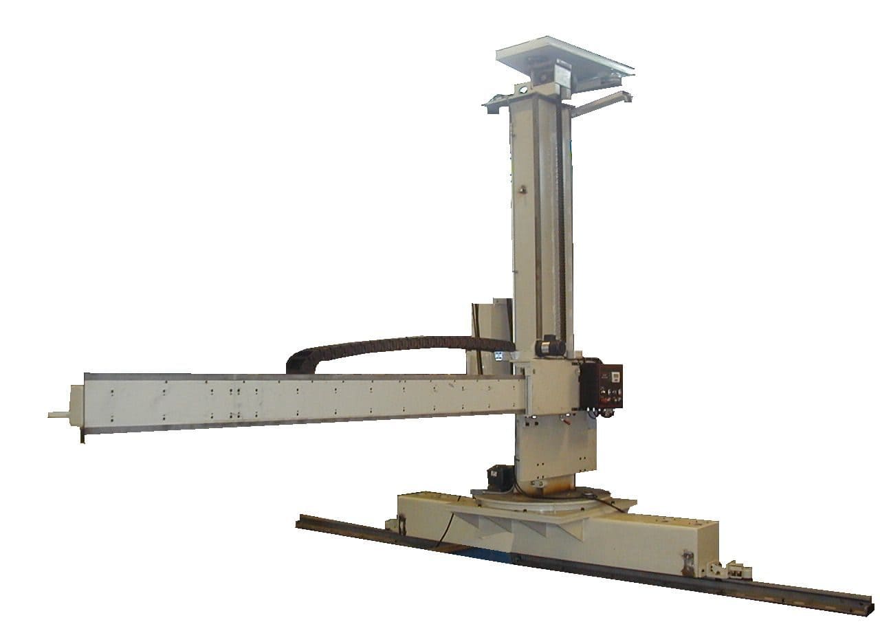
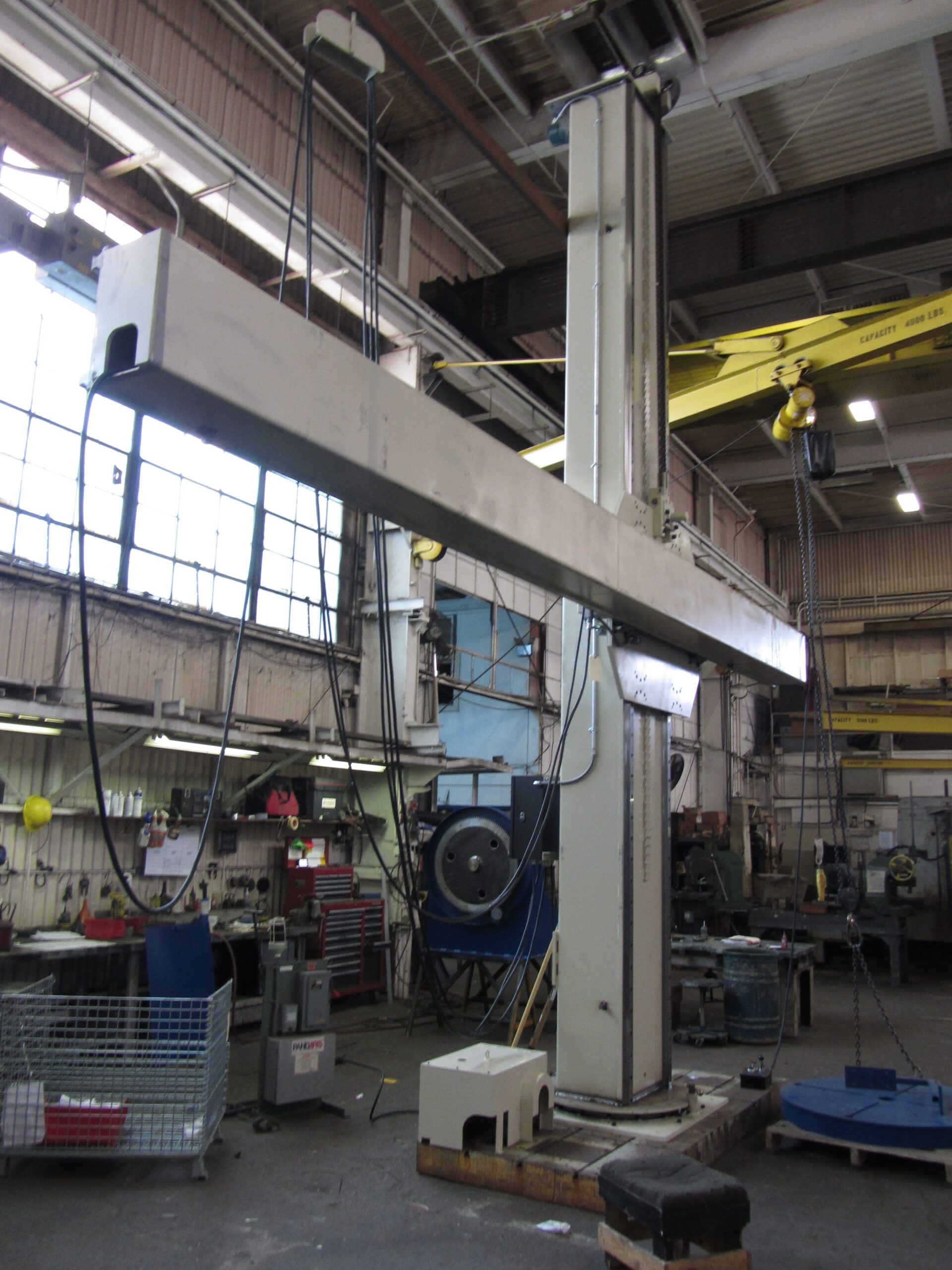
A welding manipulator column and boom — sometimes referred to as a column-and-boom welding system, boom welding manipulator, or welding column boom — is a mechanised torch positioning system consisting of a vertical column (mast) and a horizontal boom arm. The combination provides two-axis (XY) positioning of the welding torch or weld head over a stationary or slowly rotating workpiece.
The vertical column carries a motorised carriage that travels up and down under inverter-controlled drive. Mounted to this carriage is the horizontal boom, which extends inward or outward to place the torch at any point within the working envelope. A cross-slide or torch manipulation head at the boom tip provides fine adjustment of arc gap and travel angle.
Core Components at a Glance
- Column (Mast): Fabricated from heavy structural steel, stress-relieved and precision-machined; provides vertical travel. Floor- or track-mounted.
- Vertical Carriage: Rides on precision-ground linear guides or rack-and-pinion drives; supports the boom assembly.
- Boom Arm: Extends horizontally from the carriage; must be sized to reach beyond the maximum workpiece radius with capacity to spare.
- Boom Carriage: Drives the horizontal in/out travel of the boom relative to the column.
- Torch / Weld Head Mounting: Accepts MIG, TIG, SAW, plasma, or overlay weld heads; cross-slide and tilt adjustment standard on most models.
- Drive System: AC inverter drives (Siemens, Danfoss, or Allen-Bradley) providing stepless, repeatable speed control.
- Control System: PLC-based with pendant, remote joystick, HMI touch-screen, or full CNC interface options.
The term welding manipulator can refer to any device that positions a welding torch. In industrial welding, column and boom manipulator specifically denotes a floor-standing, two-axis (XY) system — as distinct from a bench-top torch manipulator or a robot arm.
2. How Does a Column and Boom Welding Manipulator Work?
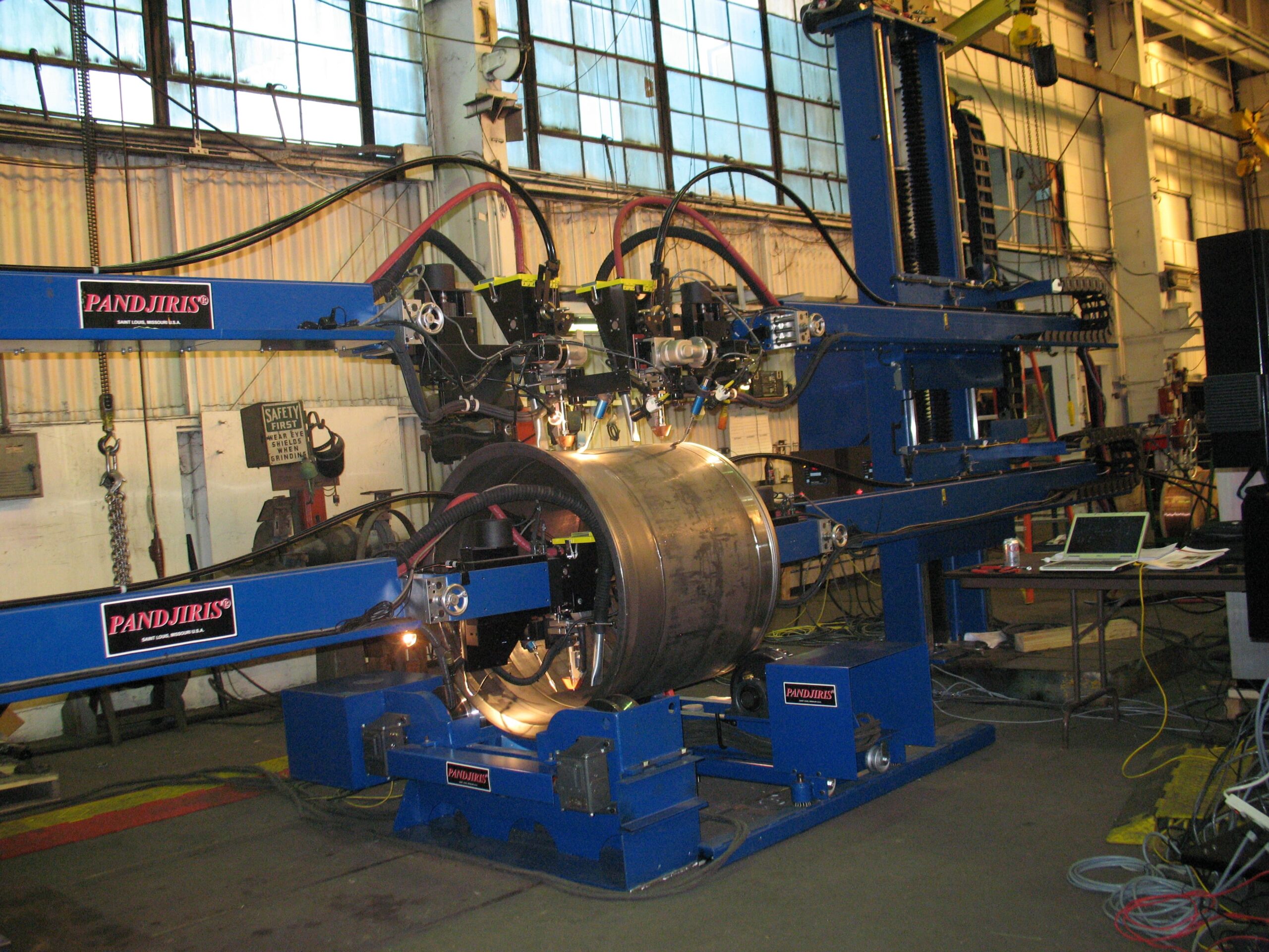
The operating principle is elegant in its simplicity. The column-and-boom manipulator is positioned alongside the workpiece — typically used in tandem with a welding rotator or welding positioner that rotates or tilts the component. The manipulator's boom is extended to place the welding torch directly over the weld joint, and the torch remains in a fixed, optimised position while the workpiece rotates beneath it.
This approach converts what would otherwise be an all-position weld into a flat-position weld — a technique strongly endorsed by the American Welding Society (AWS) and the International Institute of Welding (IIW) for improving deposition rates, bead geometry, and metallurgical properties.
Circumferential seam welding of a pressure vessel shell course using a column-and-boom manipulator paired with a welding rotator can achieve SAW deposition rates of 15–25 kg/hr per wire — compared to 3–5 kg/hr using manual SMAW. This difference directly impacts delivery schedules and fabrication cost-per-metre.
Synchronised Motion Control
On modern systems, the rotator's turning speed and the manipulator's boom travel speed are synchronised through a shared PLC or coordinated motion controller. This ensures that the weld travel speed at the joint surface remains constant regardless of workpiece diameter — a critical requirement for maintaining the correct heat input as specified in the ASME Boiler and Pressure Vessel Code, Section IX qualified welding procedure specifications (WPS).
3. Types of Column and Boom Welding Manipulators
Suppliers such as Keyplant, LJ Welding, and IRCO Automation categorise their column-and-boom product lines into several main configurations. Understanding these types is the first step in specifying the correct system.
3.1 Fixed (Floor-Mounted) Column Manipulator
The most cost-effective and rigid configuration. The column base is bolted directly to a reinforced concrete floor pad. Workpieces are brought to the machine. Ideal for dedicated welding bays processing similar-sized components — pressure vessel heads, flange assemblies, or pipe spools in a fixed work station. The fixed column offers the highest structural rigidity, making it the preferred choice for heavy SAW applications where boom deflection must be minimised.
3.2 Travelling Column Manipulator (Rail-Mounted)
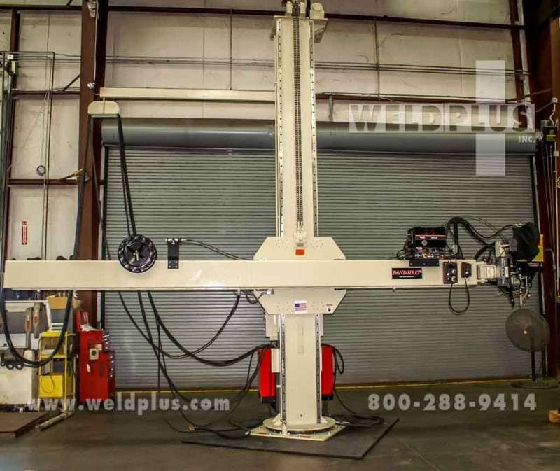
The column is mounted on a floor-level rail track, allowing longitudinal travel along the length of the workpiece. This is the standard configuration for longitudinal seam welding of wind tower sections, storage tank shell courses, and structural beams exceeding 3 metres in length. Travel speeds along the track are typically 10–3,000 mm/min, synchronised with a seam-tracking system or simply programmed for the required weld travel speed.
Redrock Automation and LJ Welding both offer extended-travel trackway systems with column travel lengths up to 50 metres for wind tower production lines.
3.3 Telescopic Mast Manipulator
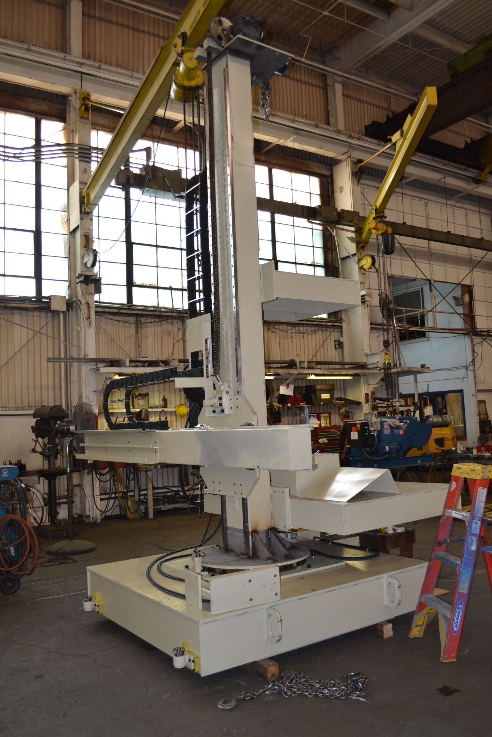
In this compact variant, the boom is housed within a telescoping mast — reducing the floor footprint significantly when the boom is retracted. Popular in offshore fabrication yards, shipbuilding facilities, and workshops where available headroom or floor space is limited. Vertical travel is achieved by extending or retracting the inner mast sections.
3.4 Cross-Carriage (XY + Cross-Slide) Manipulator
The most flexible standard configuration. In addition to vertical column travel and horizontal boom travel, a lateral cross-slide on the boom tip provides a third axis of torch positioning — effectively a Z-axis traverse. This allows the operator to fine-position the torch across the weld joint without repositioning the column, and is indispensable for multi-pass fillet welds, offset joint geometries, and twin-wire SAW applications.
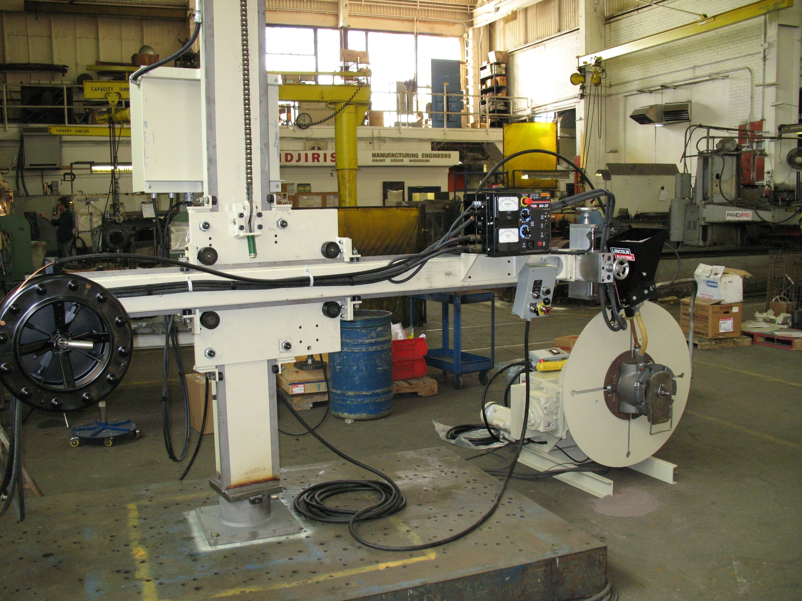
For SAW circumferential welding on vessels with varying shell course diameters, always specify a cross-slide with at least ±150 mm lateral travel. This accommodates diameter changes between shell courses without repositioning the entire column.
4. Technical Specifications
The following table presents representative specification ranges for industrial column and boom welding manipulators. Actual values depend on the manufacturer and custom configuration.
| Parameter | Standard Range | Heavy-Duty Range | Notes |
| Column Height (Total) | 2 m – 6 m | 6 m – 14 m | Taller columns for wind towers & large vessels |
| Boom Reach | 1 m – 4 m | 4 m – 10 m | Must exceed max workpiece radius |
| Vertical Travel Speed | 10 – 1,000 mm/min | 10 – 2,000 mm/min | Variable via inverter; slow end critical for TIG |
| Horizontal Travel Speed | 10 – 1,500 mm/min | 10 – 3,000 mm/min | Matched to weld travel speed requirements |
| Boom Load Capacity | 50 – 150 kg | 150 – 500 kg | Includes torch, wire feeder, flux hopper, cables |
| Welding Processes | SAW · MIG/MAG (GMAW) · TIG (GTAW) · Plasma (PAW) · Cladding | Multi-process heads available | |
| Travel Accuracy (Repeatability) | ± 0.5 mm | ± 0.1 mm | Servo-driven systems achieve tighter tolerance |
| Column Travel (Rail) | Up to 12 m | Up to 60 m+ | For longitudinal seam welding production lines |
| Power Supply | 415V / 3-phase / 50 Hz standard; 460V / 60 Hz (North America) | CE / UL / CSA certification options | |
| Control Interface | Pendant · Remote Joystick · Touch-screen HMI · CNC / PLC | Siemens S7, AB ControlLogix common |
For SAW applications specifically, boom load capacity is the single most critical specification. A typical single-wire SAW weld head, wire drive unit, flux hopper (15 kg loaded), and cable harness can weigh 80–120 kg at the boom tip. At full extension, this load creates significant bending moment on the boom structure — always request a detailed deflection calculation from the supplier. Both Keyplant and IRCO Automation publish boom deflection curves as standard in their product documentation.
5. Industrial Applications of Welding Manipulator Column and Boom Systems
The versatility of the column and boom welding manipulator makes it suitable across virtually every sector of heavy manufacturing. Below are the primary application areas, along with the relevant industry standards and typical welding processes.
5.1 Pressure Vessel & Heat Exchanger Fabrication
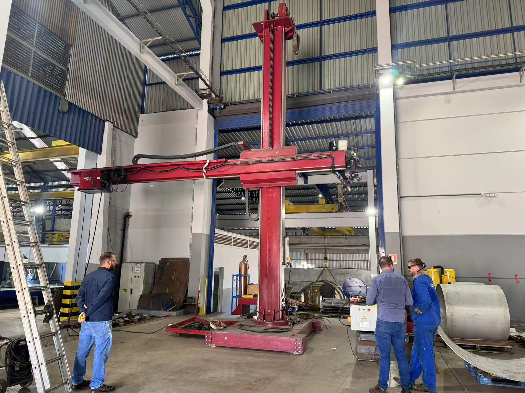
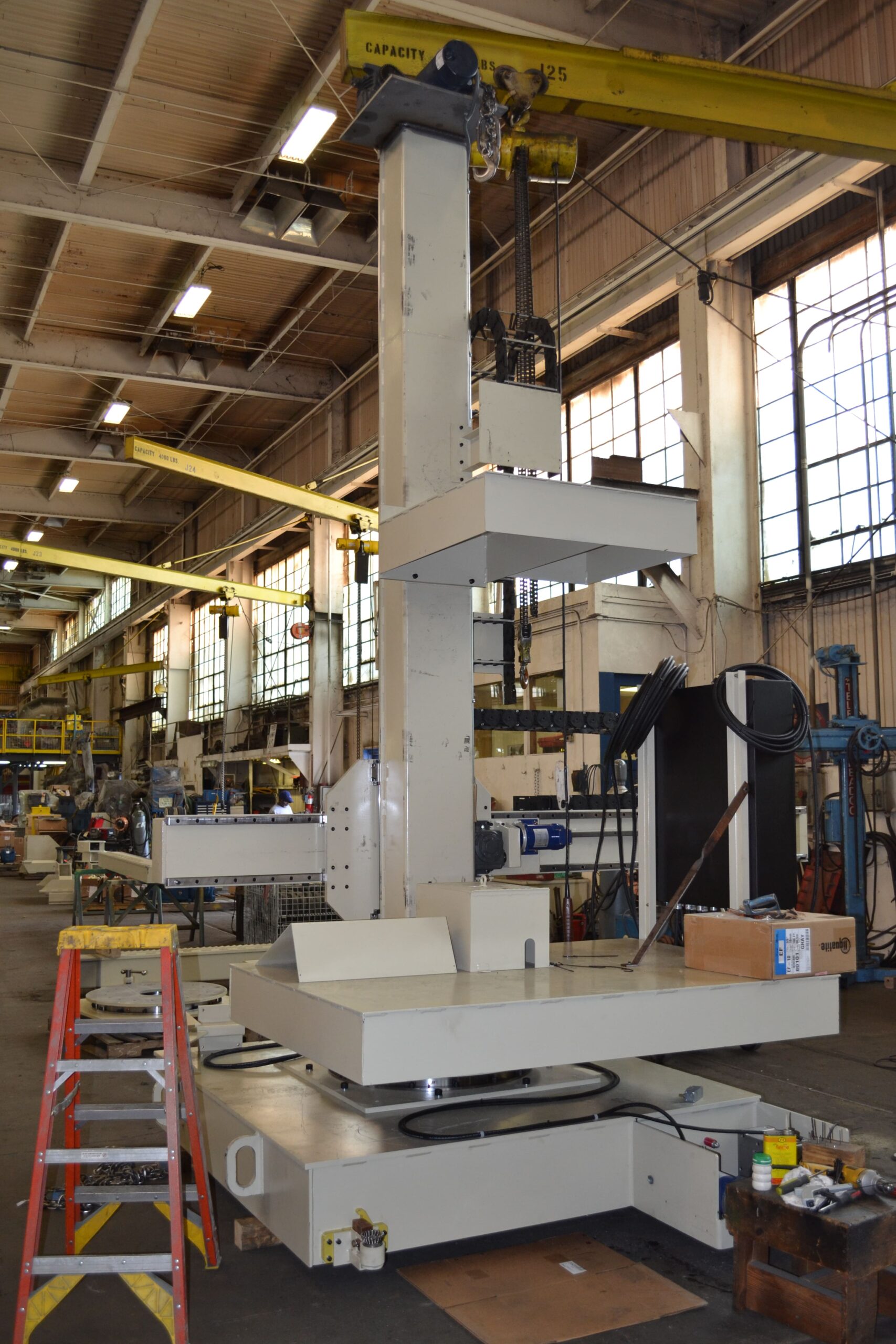
The highest-volume application for column-and-boom manipulators worldwide. Circumferential seam welding and longitudinal seam welding of pressure vessel shell courses, heads, and nozzle connections using SAW or MIG. Governed by ASME VIII (USA/Canada), EN 13445 (Europe), and EN ISO 14731 welding coordination requirements.
5.2 Wind Tower Manufacturing
Among the most demanding applications: welding longitudinal seams on conical or cylindrical tower sections up to 30 m long and 6 m in diameter. Requires travelling-column systems with extended trackways, high-duty-cycle SAW weld heads, and precise seam-tracking. A single tower section may require 200+ metres of continuous weld — fully automated column-and-boom production lines are essential for viability. Reference: DNV-ST-0126 (Support Structures for Wind Turbines).
5.3 Pipeline & Pipe Spool Fabrication
Automated butt welding of pipe spools and mainline pipe sections using column-and-boom manipulators paired with self-aligning or conventional welding rotators. Typical processes: SAW for root and fill passes on thick-wall pipe; TIG hot-pass for X65/X70 grade CRA-clad or duplex stainless steel pipe. Applicable codes include API 1104 and ASME B31.3.
5.4 Storage Tank Construction
Shell course seam welding for above-ground storage tanks per API 650 (USA) and EN 14015 (Europe). Large-diameter tanks (up to 100 m+) require travelling-column systems on extended trackways running the full circumference of the tank erection area.
5.5 Structural Steel & Heavy Engineering
Fillet and butt welding of welded I-beams, box girders, bridge components, crane girders, and offshore structural members. Typically MIG/MAG or SAW with multi-wire configurations to maximise deposition. Governed by AWS D1.1 (USA) or EN ISO 3834 quality requirements for fusion welding.
5.6 Shipbuilding & Offshore
Block assembly welding, hull panel line welding, jacket structure fabrication, and spool piece welding for floating production units (FPSOs). Governed by classification society rules: DNV, Lloyd's Register, Bureau Veritas, and ABS.
5.7 Railway & Defence
Bogie frame welding, armour plate assembly, military vehicle hull welding, and large rail infrastructure component fabrication — often requiring high-integrity MIG or TIG welding with full NDE traceability.
6. Column and Boom Manipulator vs. Alternative Equipment
Selecting the right welding automation solution requires understanding where a column-and-boom manipulator excels and where alternative equipment may be more appropriate.
| Equipment Type | Ideal Application | Limitation vs. Column & Boom |
| Column & Boom Manipulator | Large/long workpieces; high reach; SAW; automated seam welding | — |
| Welding Positioner | Small–medium asymmetric components; tilt & rotate positioning | Limited reach; unsuitable for very long workpieces |
| Welding Rotator | Cylindrical pipes & vessels; continuous rotation; all diameters | No torch positioning — must be combined with a manipulator |
| Articulated Welding Robot | Complex 3D geometries; short weld seams; high mix / low volume | Payload limited for SAW; high programming cost; complex cell integration |
| Manual Welding Tractor | Simple single-pass fillet welds; site & field applications | No torch positioning; limited process control; operator dependent |
As Lincoln Electric's SAW reference guide notes, for high-deposition seam welding applications with payloads exceeding 50 kg at the torch, the column-and-boom manipulator remains the preferred solution — articulated robots being impractical at such payload levels and articulation spans.
7. How to Select the Right Welding Manipulator Column and Boom
Use the following structured checklist when specifying your system. These criteria reflect the evaluation process used by major EPC contractors and fabricators in Europe, North America, and the Asia-Pacific region.
Step 1 — Define Your Workpiece Envelope
- Maximum workpiece diameter (drives minimum boom reach)
- Maximum workpiece height (drives minimum column travel height)
- Maximum workpiece length (determines whether a travelling column is required)
- Maximum workpiece weight (for rotator and positioner sizing — not directly for manipulator)
Step 2 — Specify Your Welding Process
- SAW (Submerged Arc): Boom load capacity typically 100–300 kg; flux recovery system integration; high duty cycle drives
- MIG/MAG (GMAW): Boom load 50–100 kg; wire feeder mounting; gas hose routing
- TIG (GTAW): Boom load 30–80 kg; precise low-speed control (as low as 5 mm/min)
- Plasma / Laser Overlay: Specialised torch cooling, gas supply routing, and motion accuracy requirements
Step 3 — Determine Travel Speed Requirements
- SAW: typically 150–600 mm/min weld travel speed
- MIG/MAG: typically 200–900 mm/min
- TIG: typically 50–300 mm/min
- Confirm the drive system achieves stable speed at the lower end of the range — stepless inverter control is essential
Step 4 — Integration Requirements
- Synchronisation with rotator or positioner — confirm compatible PLC I/O protocols (e.g., Profibus, EtherNet/IP, Profinet)
- Arc length control (AVC) or seam tracking integration
- Wire feeder and welding power source interface
- Flux delivery and recovery system (SAW)
Step 5 — Certification & Market Requirements
- EU / UK: CE marking per Machinery Directive 2006/42/EC; Low Voltage Directive; EMC Directive
- USA: UL 508A panel certification; OSHA compliance per 29 CFR 1910.212
- Canada: CSA Z432 machinery safeguarding; electrical panel to CSA C22.2
- All markets: IEC 60204-1 (Safety of electrical equipment of machines)
Always request a formal boom deflection analysis at full extension under maximum payload — specified in millimetres at the boom tip. Industry best practice (as observed in Keyplant and IRCO Automation product documentation) is to limit boom tip deflection to less than L/500 (where L = boom length in mm). Excessive deflection causes arc length variation that directly affects weld bead geometry and may invalidate your WPS.
8. Integration with Welding Rotators & Positioners
A welding manipulator column and boom reaches its full potential when integrated into a complete automated welding cell. The two most common integration configurations are:
8.1 Column & Boom + Welding Rotator
The most common automated cell configuration for cylindrical components (vessels, drums, pipes). The welding rotator rotates the workpiece at a controlled, adjustable speed; the manipulator holds the torch stationary at the 12 o'clock (or 1–2 o'clock) optimal welding position. The rotator speed is synchronised to deliver the correct weld travel speed at the joint surface regardless of workpiece diameter.
Our range of conventional welding rotators and self-aligning welding rotators are fully compatible with our column-and-boom systems, including synchronised motion control through a shared master PLC.

8.2 Column & Boom + Welding Positioner
For asymmetric or non-cylindrical components — flanged assemblies, valve bodies, nozzle connections — a welding positioner tilts and rotates the workpiece to present the weld joint in the flat or horizontal-fixed position, while the boom delivers the torch to the joint. Our head-and-tailstock positioners and turntable positioners are designed for seamless integration with our manipulator range.
9. Safety Standards & Regulatory Compliance
All column-and-boom welding manipulators intended for industrial use must comply with applicable machinery safety and electrical standards. The following are mandatory or strongly recommended for equipment supplied to EU, North American, and international markets:
| Standard / Directive | Scope | Market |
| Machinery Directive 2006/42/EC | CE marking; essential health & safety requirements for machinery | EU / UK |
| IEC 60204-1 | Safety of electrical equipment of machines; wiring, e-stops, drive systems | Global |
| ISO 10218-1 / -2 | Safety requirements for industrial robots & automated welding cells | Global |
| OSHA 29 CFR 1910.212 | General machine guarding; risk reduction in US manufacturing facilities | USA |
| CSA Z432 | Safeguarding of machinery; Canadian mandatory standard | Canada |
| EN ISO 14731 | Welding coordination — tasks and responsibilities | EU / Global |
| EN ISO 3834 | Quality requirements for fusion welding — quality management system | EU / Global |
10. Frequently Asked Questions
What is the difference between a welding manipulator column and boom and a welding positioner?
A welding manipulator column and boom positions the torch or weld head — it moves the welding equipment to the joint. A welding positioner positions the workpiece — it rotates and/or tilts the component to present the weld joint in the optimum orientation. In most automated welding cells, both are used together: the positioner or rotator moves the workpiece while the manipulator keeps the torch precisely at the joint.
What welding processes are compatible with a column and boom welding manipulator?
Column-and-boom manipulators are process-agnostic. They are routinely configured for Submerged Arc Welding (SAW), MIG/MAG (GMAW), TIG (GTAW), Plasma (PAW), narrow-groove TIG, cold-wire TIG overlay, and laser-hybrid welding. The key constraint is the boom load capacity — SAW configurations with twin-wire weld heads and flux hoppers may require 150–300 kg boom capacity, while TIG setups typically require only 30–60 kg.
How do I calculate the required boom reach for my application?
The minimum boom reach equals the maximum workpiece radius + 300–500 mm clearance. For a vessel shell with a maximum outside diameter of 3,000 mm, the minimum boom reach is 1,500 + 400 = 1,900 mm. Always specify headroom for the torch assembly, cross-slide travel, and any seam-tracking sensor offset. When in doubt, size up — a longer boom on a stiffer structure is preferable to a boom at the very limit of its reach.
Can the column and boom manipulator be synchronised with a welding rotator?
Yes — this is standard practice in all modern automated welding cells. The rotator's peripheral speed (mm/min at the workpiece surface) is matched to the WPS-required weld travel speed. On PLC-controlled systems, a master/slave relationship ensures that if the rotator speed is adjusted, the manipulator's boom travel speed is proportionally corrected. Refer to the AWS D1.1 code requirements for weld procedure qualification to understand why maintaining consistent travel speed is critical.
What is the typical lead time for a column and boom welding manipulator?
Standard configurations with commonly stocked column heights (2–4 m) and boom lengths (2–4 m) typically carry lead times of 4–8 weeks. Heavy-duty or bespoke systems — large column heights, extended boom reaches, special SAW configurations, or travelling-column systems with custom trackways — typically require 10–20 weeks from order placement. Always confirm lead time in your purchase order, as delays in welding automation equipment frequently impact production start dates for major fabrication projects.
Are your column and boom manipulators CE certified for the European market?
Yes. Our welding manipulator column and boom systems are CE marked in accordance with Machinery Directive 2006/42/EC, with supporting documentation including technical file, Declaration of Conformity, risk assessment, and operating manuals. UL/CSA-certified variants for the United States and Canadian markets are available upon request.
What is the difference between a fixed column and a travelling column manipulator?
A fixed column is bolted permanently to the floor — the workpiece is brought to the machine. It offers maximum structural rigidity and is the most cost-effective solution for short or medium-length components. A travelling column is mounted on a floor-level rail track, allowing the manipulator to travel longitudinally along the length of the workpiece. This is essential for welding long cylindrical components such as wind tower sections, tank shell courses, or structural beams exceeding approximately 3 metres in weld length.
11. Industry References & Further Reading
- American Welding Society (AWS) — Standards, Codes & Technical Guides
- International Institute of Welding (IIW) — Best-Practice Welding Guidelines
- The Welding Institute (TWI) — Welding & Joining Technology Research
- ASME Boiler & Pressure Vessel Code (BPVC) — Section VIII & IX
- Lincoln Electric — Submerged Arc Welding Process Reference
- ESAB — What Is Submerged Arc Welding?
- Keyplant — Welding Automation Equipment (Sweden)
- IRCO Automation — Welding Positioners & Manipulators (USA)
- LJ Welding Automation — Column & Boom Systems (Canada)
- Red-D-Arc Welderentals — Welding Automation Rental & Sales (North America)
- European Commission — Machinery Directive 2006/42/EC
- ISO — EN ISO 14731: Welding Coordination
Column & Boom Systems — In the Field

Ready to Automate Your Welding Operation?
Talk to our engineering team about your column-and-boom welding manipulator requirements — standard or fully bespoke. No-obligation technical consultation and detailed quotation provided.