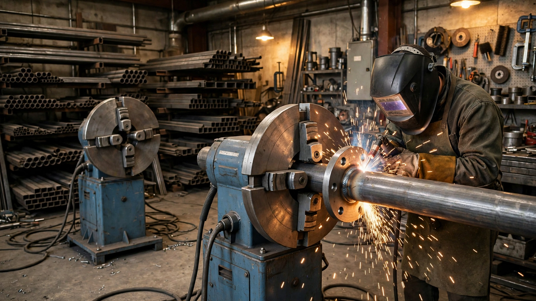
A pipe spool shop wins or loses its margin on circumferential seams. The seam takes minutes; setup, rework, and welds that wander off the joint take hours. The difference is usually the workholding: a centred, firmly gripped workpiece rotated at a steady speed lets the welder work in the flat position. That is the job of a welding chuck.
Short Answer
Choose the chuck by the workpiece first. Start with the smallest and largest outside diameters in the mix, the weight including flanges and fittings, how far the centre of gravity sits from the faceplate and from the rotation axis, and whether long pipe must pass through the chuck. Then pick the family: WP is the general-purpose welding chuck for pipe, flange, and elbow work; WPT is the large through-hole variant for big-diameter pipe that must pass through; K11 is the standard three-jaw self-centring chuck for smaller, precise, repeatable round work. If the workpiece is square, rectangular, irregular, or deliberately eccentric, none of the three self-centring families is right on its own — that job needs a four-jaw independent chuck or a custom fixture. A chuck does not replace the positioner — the positioner provides rotation and tilt, the chuck provides centring and grip — so buy them as a combination and check the chuck’s weight against the positioner’s rated moment as well as its rated load.
What a Welding Chuck Does That a Faceplate Cannot
A faceplate is a flat, rotating table, usually with T-slots or a bolt-hole pattern. It is excellent at one thing: giving a flat workpiece or a fixture a surface to bolt to. It does not centre anything by itself: the operator locates the part, clamps it, and checks it — and does it all again on the next part.
A chuck works differently. Its jaws close radially onto the workpiece, and in a self-centring chuck they all move together, driven by a spiral scroll plate inside the chuck body. One turn of the chuck key moves every jaw the same distance, so a round workpiece is pulled onto the axis of rotation automatically. That is the core difference: a faceplate holds a part where you put it, while a self-centring chuck puts a round part on the axis for you.
The consequences are speed, repeatability, and grip. Changeover on a round pipe takes seconds: open the jaws, swap the pipe, close the jaws, and the next part is centred the same way as the last. The chuck also grips with radial force all around the circumference, resisting torque and tilt loads better than a few clamps on a flat plate — and where it has a through-hole, a long pipe can pass through and be supported behind the positioner, which no faceplate can do.
The table below compares the three holding methods on function rather than habit: a chuck is fastest for round work, a faceplate is still needed for flat assemblies, and a fixture plate earns its cost only when the same part repeats.
| Feature | Welding chuck | Faceplate | Fixture plate |
|---|---|---|---|
| Centring | Self-centring (3-jaw) or dialled in (4-jaw); round work lands on the rotation axis | None; operator locates and checks the part | Located by stops or pins; repeatable for one part family |
| Grip | Radial jaws around the circumference; resists torque and tilt loads | Clamps or bolts from the face; grip depends on clamp placement | Clamps arranged for the specific part; very secure for that part only |
| Through-hole for pipe | Yes on WPT and most K11 sizes; long pipe can pass through | No | No, unless designed in |
| Changeover speed | Fast for round parts in range | Slow; each part is located and clamped by hand | Fast for its part; slow or impossible for other parts |
| Best for | Pipe, flanges, elbows, nozzles, round and hex bar | Flat assemblies, frames, buckets, irregular weldments | Repeat production of one part or part family |
| Main limitation | Limited diameter range; wrong for flat or very large assemblies | No automatic centring; slow and operator-dependent | Cost and lead time; only pays back on volume |
These are complements, not substitutes. A shop welding pipe spools and structural frames needs a chuck for the pipe and a faceplate or fixture plate for the frames, ordered with the interface — flange mounting and T-slots — that accepts both. Buying only a faceplate and struggling to centre pipe on it is paid for in setup time on every part.
How a Welding Chuck Works
Inside a three-jaw self-centring chuck sits a scroll plate: a flat spiral gear. Each jaw has teeth on its underside that engage the spiral. Turning the chuck key rotates the scroll, driving all three jaws inward or outward by exactly the same amount. Because the jaws are spaced 120 degrees apart and move together, a round workpiece is centred on the chuck’s axis as the jaws close — centring built into the mechanism, not into the operator’s skill.
Jaws come in two sets: internal jaws for gripping the outside of a part, and external (reversed) jaws for gripping a bore or a larger outside diameter. Reversing the jaws changes the clamping range, so every chuck has an inside and an outside clamp range, and both must be checked. Jaws are numbered and must return to their matching slots; a jaw in the wrong slot will not track with the others. Hard jaws are the default for steel pipe; soft jaws can be machined to the part diameter for thin-wall tube or finished surfaces.
A four-jaw chuck works on a different principle. Each jaw has its own screw and moves independently, so there is no automatic centring at all. The operator sets each jaw with a dial indicator until the workpiece runs true. It is slower — minutes rather than seconds per setup — but it can hold square, rectangular, and irregular shapes, and a round part deliberately off-centre.
The through-hole is the third thing to understand. Many chucks have a hole through the centre of the body, so a pipe can pass through the chuck and out the back of the positioner. Its size sets the largest pipe that can be fed through. A long spool needs a large hole plus a roller support behind the positioner to carry the overhang, Re-check the grip after the first weld passes.
WP vs WPT vs K11: The Three Families
MISA lists three welding chuck families — WP, WPT, and K11 — all manual, flange-mounted chucks for welding positioners, differing in size range, through-hole, and intended duty.
The WP series is the general-purpose welding chuck. Distributor-published data lists models from WP-200 to WP-750, with capacities from 30 kg to 1,200 kg and outside clamp ranges from about Ø110–210 mm up to Ø550–800 mm; extended ranges up to Ø1,500 mm are listed with special jaws. Supplier descriptions emphasise a light, thin body, claiming the reduced thickness shortens the distance between workpiece and machine and improves loading capacity — treat that as a supplier claim, not a measured specification. Confirm ranges and capacities with MISA for the model quoted.
The WPT series is the large through-hole variant: it exists for bore, not for weight. Distributor-published data lists two models, WPT-600 and WPT-1000, both rated at 1,000 kg capacity. The difference is the clamp range: WPT-600 grips from Ø85 mm inside to Ø615 mm outside, while WPT-1000 reaches Ø85 mm inside to Ø1,050 mm outside. Choosing the WPT-1000 buys diameter range and through-hole capacity, not extra load capacity.
The K11 series is the standard three-jaw self-centring scroll chuck, used across lathes, mills, and welding positioners. It is supplied with internal and external jaws, and soft jaws are available on request. Typical through-hole values are about 40 mm at K11-160, 65 mm at K11-200, 80 mm at K11-250, 100 mm at K11-315, and up to 260 mm at the largest K11-630 sizes; new K11 chucks are typically listed with an accuracy of 0.05 mm or better. The K11 is the economical, precise option for small round work; once the pipe is large or long, the WP or WPT families take over.
The table below compares the three families on the axes that decide the purchase — through-hole, capacity, and intended duty — because on diameter alone they overlap and there is no clear winner.
| Feature | WP series | WPT series | K11 series |
|---|---|---|---|
| Type | 3-jaw welding chuck for positioners | 3-jaw large through-hole welding chuck | 3-jaw self-centring scroll chuck |
| Typical capacity (distributor-published) | 30 kg (WP-200) to 1,200 kg (WP-750) | 1,000 kg (both WPT-600 and WPT-1000) | Small to medium; confirm per model |
| Outside clamp range | About Ø110–210 mm (WP-200) to Ø550–800 mm (WP-750) | Ø170–615 mm (WPT-600); Ø170–1,050 mm (WPT-1000) | Depends on size; K11-200 covers roughly Ø6–200 mm |
| Through-hole | Small to moderate; check per model | Large; the defining feature of the family | Modest; typically 40 mm (K11-160) to 100 mm (K11-315) |
| Best for | General pipe, flange, and elbow work | Large-diameter pipe, especially long pipe that must pass through | Small, precise, repeatable round work |
| Main limitation | Limited through-hole for long pipe | Same 1,000 kg capacity on both models; large and heavy | Limited diameter and through-hole |
Choose by the constraint that bites first. If the pipe must pass through, the WPT wins regardless of weight. If the work is small and repeatable, the K11 wins on cost and precision. Otherwise the WP is the general default — but check it against the sizing rules next, because a WP that covers the diameter may still be wrong on weight or eccentricity.
Sizing a Chuck: Diameter, Weight, and Eccentricity
Sizing a chuck has four steps, in order: diameter, weight, eccentricity, through-hole. Skipping a step is how a chuck that fits the pipe still fails in service.
Diameter is the range check. List the smallest and largest outside diameters in the mix, and check both against the chuck’s inside and outside clamp ranges — not just the largest. A chuck that grips the Ø400 mm pipe but cannot close down to the Ø120 mm nipple will force a second chuck, a jaw change, or manual welding for the small work.
Weight is the load check, and it has two parts. First, the workpiece weight including flanges, fittings, and any attached valves or nozzles — the part as it will actually be lifted onto the positioner, not the bare pipe. Second, the chuck’s own weight, which counts against the positioner’s capacity: a positioner rated at 3,000 kg does not have 3,000 kg available for the workpiece if the chuck and fixture weigh 300 kg. MISA’s project documentation says explicitly to consider eccentricity and centre of gravity when choosing a model, and capacity is published as a range (300 kg to 50,000 kg) because the real limit depends on the load geometry.
Eccentricity is the check most buyers miss, and it is the one that causes sudden failures. A positioner’s rating is a moment, not a weight: the safe load falls as the centre of gravity moves away from the faceplate, and falls sharply when it is offset from the axis of rotation. A 240 kg valve body with its centre of gravity 180 mm off the axis puts a continuous overturning moment on the drive and the chuck for every revolution; the same 240 kg centred on the axis is a routine load. Mass, centre-of-gravity distance, and eccentric moment are the three quantities that govern whether a part can be rotated safely.
Through-hole is the handling check. If the pipe is longer than the space between the chuck and the end of the shop, or the spool must be welded at several stations along its length, the pipe needs to pass through the chuck. The through-hole must exceed the pipe outside diameter with clearance for ovality and weld reinforcement, and a roller support behind the positioner must carry the overhang. If there is no room behind the positioner for the pipe to extend, a through-hole chuck does not solve the problem — the layout does.
The sizing table below gives starting points, not answers: it stops the most common error, buying by diameter alone, by putting weight and eccentricity checks in the same row as the recommendation.
| Workpiece band (example) | Starting chuck family | Checks before ordering |
|---|---|---|
| Small pipe and fittings, Ø20–200 mm, under 100 kg | K11 (K11-160 to K11-250) | Smallest diameter in the mix; through-hole if pipe is long |
| Medium pipe and flanges, Ø100–400 mm, 100–300 kg | WP (WP-300 to WP-400) | Largest and smallest diameters; weight with flanges; centre-of-gravity distance |
| Large pipe and flanges, Ø250–600 mm, 300–1,000 kg | WP-500 / WP-600 or WPT-600 | Through-hole need; eccentric moment; chuck weight vs positioner moment |
| Very large pipe, Ø500–1,050 mm, up to 1,000 kg | WPT-1000 | Pipe must pass through; roller support; floor space for overhang |
| Square, rectangular, or eccentric parts, any size | 4-jaw independent chuck or custom fixture | Indicating time per part; counterweight or tailstock support |
Diameter picks the family, but weight and eccentricity pick the size — and can move the choice to a different family altogether. Always size from the heaviest and most eccentric recurring part, not from the average part.
Application Matrix: Which Combination for Which Job
A chuck is rarely bought alone: it comes as a combination with a positioner, sometimes plus a tailstock, roller support, or rotator. The matrix below maps common jobs to combinations that work — the same chuck on the wrong positioner is still the wrong purchase.
| Application | Workpiece | Chuck + positioner combination | Why it works |
|---|---|---|---|
| Pipe spool, circumferential butt joints | Pipe Ø100–400 mm, 1–3 m long, with flanges | WP chuck on a tilting positioner; roller support behind | Chuck centres the pipe; tilt brings each joint to the flat position; roller carries the tail |
| Long pipe, multiple joints | Pipe Ø300–900 mm, 6–12 m long | WPT chuck on a headstock positioner; tailstock or roller support at the far end | Through-hole lets the pipe feed through; far-end support stops sag and runout |
| Flange welding, small batch | Flanges and short nipples, Ø50–250 mm | K11 chuck on a small tilting positioner | Fast changeover and good concentricity on small round parts |
| Elbow and nozzle welding | Elbows, tees, nozzles with offset branches | 4-jaw independent chuck on a tilting positioner; indicate each part in | Independent jaws hold the irregular shape and set the branch on the axis |
| Valve body or pump housing | Irregular casting, 100–300 kg, eccentric | 4-jaw chuck or custom fixture, with a counterweight check | Grip is set to the casting; eccentric moment is checked |
| Excavator bucket or frame | Large flat or irregular weldment | Faceplate with T-slots, or L-type positioner — not a chuck | The part needs location on a datum, not radial grip |
| Long vessel or wind tower section | Cylinder Ø1–4 m, several tonnes | Welding rotator (turning rolls), not a chuck | The cylinder rests on rolls and rotates by friction; gripping it would distort it |
Start from the joint and the handling, not from the chuck catalogue. If the job is a long cylinder, the welding rotator is the right machine and the chuck question disappears. If the job is a spool with several joints, quote the through-hole and roller support together with the chuck.
Chuck and Positioner Combinations
The most common combination is a chuck on a tilting welding positioner, which rotates 360 degrees and tilts typically 0–120 degrees so the joint can be welded flat. The register — the machined spigot locating the chuck concentrically on the faceplate — must match, with the bolt circle checked when both are ordered: a damaged register shows up as runout no jaw adjustment can fix. For long pipe, add a height-adjustable roller support or a headstock–tailstock setup, as in MISA’s welding positioner projects: a machine for elbow pipe used a 1,500 mm faceplate with six T-slots to fix a chuck, the tailstock travelling on a rail. Grip at one end, support at the other, and never let a long pipe hang from the chuck alone. Hydraulic lifting adds up to 800 mm of stroke on a published 3-ton example; control is by wired (25 ft) or wireless (300 ft) pendant, power 110–600 V.
Maintenance and Jaw Wear
A chuck is a precision mechanism working in the worst environment in the shop: welding spatter, grinding dust, heat, and impact loading. It loses accuracy gradually, and the loss shows up first as weld defects, not as a broken part.
Clean the chuck after every use. Brush spatter and chips out of the jaw slides and the scroll area, and use compressed air to clear the gaps between the jaws. Spatter left in the slides acts as an abrasive: every time the jaws move, it scores the slideways and the scroll plate. Lubricate the scroll plate and jaw slides periodically with a light machine oil or a chuck grease recommended by the chuck maker, and do not over-lubricate — excess grease attracts dust and spatter and turns into a grinding paste. A thin film is enough.
Inspect the jaws before each use and the scroll when the jaws are removed. Look for rounded or chipped gripping edges, cracks, and wear on the jaw teeth that engage the scroll. Check that each jaw is in its numbered slot and that all three jaws move together smoothly when the key is turned. If one jaw lags or sticks, stop: the scroll is contaminated or worn, and continuing will grip the part unevenly. A chuck that has been dropped can look fine and run several tenths of a millimetre out — measure it rather than assuming it.
Measure runout on a schedule, not when parts start being rejected. Chuck a ground test bar or a known-good pipe, put a dial indicator on it, and rotate the positioner by hand through 360 degrees. Record the total indicator reading and the date. A reading that grows month by month is the scroll or the jaw slides wearing — a signal to clean, re-lubricate, and if necessary replace the jaws or the chuck. Soft jaws can often be re-machined; master-jaw or scroll wear usually means replacement. Never leave the chuck key in the chuck: a key left in place becomes a projectile the moment the positioner rotates.
The failure-mode table below gives the symptoms a shop will actually see. Chuck problems are usually misdiagnosed — blamed on the welder, the positioner, or the procedure — while the chuck quietly gets worse.
| Symptom | Likely cause | What to do | Risk if ignored |
|---|---|---|---|
| Workpiece slips during rotation | Jaws not tightened enough; worn jaw edges; wrong jaw set | Tighten firmly without overtightening; replace worn jaws; check the clamp range | Seam wanders; rework; part drops or swings |
| Runout grows over weeks | Spatter and dust in the scroll; worn scroll or jaw slides; damaged register | Strip, clean, and re-lubricate; measure runout on a test bar | Inconsistent penetration; rejected joints; scrap parts |
| One jaw moves unevenly or sticks | Debris in that jaw slide; damaged jaw teeth; jaw in the wrong slot | Remove jaws, clean slides and scroll, refit in numbered slots | Uneven grip; thin-wall distortion; part held off-centre |
| Chuck is hard to turn with the key | Dry or contaminated scroll; corrosion | Clean and lubricate the scroll; free the jaws and re-check; store dry | Forced key damages the scroll; jaws seize mid-job |
| Grip loosens after the first weld passes | Workpiece expands with heat; jaws seated on scale or spatter | Clean the gripping surfaces; re-check grip after the first passes | Part shifts mid-weld; cracked or misaligned joint |
| Chuck key left in the chuck | Operator habit; no key storage at the station | Remove the key immediately after tightening; fit a spring-loaded key if available | Key becomes a projectile when the positioner rotates; serious injury |
Most chuck failures are maintenance failures — cheap to prevent and expensive to ignore. Order the spare jaw set, chuck key, and lubricant with the chuck, and put a runout check on the same schedule as the welding machine’s calibration.
When Not to Use a Chuck
Do not use a chuck for large flat assemblies, frames, or buckets: those parts need to be located on a datum and clamped from the face, and a faceplate with T-slots or a dedicated fixture is the right answer. Do not use a chuck for a long, heavy cylinder that should rest on turning rolls: a welding rotator supports the shell along its length and rotates it by friction, while a chuck gripping one end would concentrate the whole load on the jaws and risk distortion. Do not use a three-jaw self-centring chuck for square, rectangular, or irregular parts, or for work that must be deliberately eccentric — the scroll will centre the part whether that is wanted or not. Use a four-jaw independent chuck or a fixture instead. Do not use a chuck with a through-hole smaller than the pipe that must pass through it, or any chuck when the workpiece exceeds the chuck’s capacity or the eccentric moment exceeds what the positioner drive can hold.
Worked Examples
Example 1 — Pipe spool with a flange (assumptions stated). A shop welds spools from Ø168 mm pipe, 2 m long, with a Ø220 mm flange on one end. Pipe 55 kg plus flange 30 kg is 85 kg as lifted; the smallest part in the same mix is a Ø114 mm nipple. A K11-200 covers the diameters, and a WP-300 also covers the range, with a distributor-published capacity of 120 kg. But the flange sits at one end, so the centre of gravity is offset; gripped at the plain end, the flange end overhangs and the positioner sees a tilting moment that grows with the overhang. Order a WP-300 or K11-200 on a tilting positioner of at least 300 kg rated capacity, with a roller support under the flange end if the overhang exceeds about 1 m. The overhang, not the 85 kg, decides the support.
Example 2 — Eccentric valve body (assumptions stated). A shop must weld a 240 kg valve body whose centre of gravity is 180 mm from the rotation axis, because the body is cast with a heavy bonnet on one side. A three-jaw self-centring chuck would centre the outside diameter, putting the heavy side off-axis and leaving the positioner fighting a continuous overturning moment on every revolution. A bigger three-jaw chuck does not fix this: the part is still off-centre, and the bigger chuck is heavier. The answer is a four-jaw independent chuck, jaws set by dial indicator so the weld joint runs true, plus a check of the positioner’s rated eccentric moment. If it is exceeded, use a counterweight, a larger positioner, or a fixture.
Common Buying Mistakes
- Buying by chuck diameter alone. The chuck grips the largest pipe but cannot close down to the smallest, or covers the diameters and fails on weight or eccentricity. Consequence: a second chuck, jaw changes on every job, or small parts back to manual welding.
- Buying by positioner tonnage, ignoring the chuck’s weight and the eccentric moment. A 3-ton positioner has less than 3 tons available once chuck, fixture, and fittings are counted, and a centred rating says nothing about an offset load. Consequence: a stalled drive, a swinging load, and a safety incident the rating plate appeared to rule out.
- Choosing a small-bore chuck when long pipe must pass through. The pipe cannot feed through, so the shop cuts spools short and adds joints. Consequence: extra joints, welds, inspection, and lead time on every spool.
- Using a three-jaw self-centring chuck for square, rectangular, or eccentric work. The scroll centres the part and grips it on two jaws at best. Consequence: runout, slip, and welds in the wrong place.
- Gripping thin-wall tube with hard jaws at full force. The jaws dent or ovalise the tube, and the distortion remains after the weld. Consequence: a spool that does not fit up at site, or a pressure boundary that fails inspection.
- Ignoring the flange and register match. The bolt circle or register does not match, so the chuck is adapted with a makeshift plate or runs eccentrically. Consequence: runout that cannot be adjusted out, and a chuck blamed for a mounting error.
- Skipping runout checks until parts are rejected. The scroll wears gradually and runout creeps up; the first sign is a batch of joints failing inspection. Consequence: scrap, rework, and a procedure review for a fault that was in the workholding all along.
- Leaving the chuck key in the chuck. It is a habit, not a decision, and the most preventable injury in this guide. Consequence: a steel key thrown across the shop the moment the positioner rotates.
Buyer Checklist
- What are the smallest and largest outside diameters in the mix? A chuck has a fixed clamp range, and the whole mix must fit inside it — with the jaws in the configuration that will actually be used.
- Is any part gripped from the inside, and what is its bore? Internal gripping uses the reversed jaws and a different range, and the bore must be round and clean enough to grip.
- What does the heaviest assembly weigh, including flanges, fittings, and nozzles? The bare pipe weight understates the load, and the chuck and fixture add more. Check the rated moment against the total.
- Where is the centre of gravity — how far from the faceplate, and how far off the rotation axis? Distance from the faceplate sets the tilting moment; offset from the axis sets the eccentric moment.
- What is the longest pipe, and must it pass through the chuck? This decides the through-hole diameter and whether a roller support and floor space behind the positioner are needed.
- What is the material and wall thickness? Thin-wall tube distorts under hard jaws; soft or coated material marks easily; stainless needs clean jaws to avoid contamination. The jaw type follows from the material.
- What joints and weld process are involved? Circumferential butt joints, fillet welds on nozzles, and TIG root passes each put different demands on rotation speed and access.
- What positioner will the chuck mount on — model, faceplate diameter, bolt circle, and register? The chuck and the positioner are one assembly, and a mismatch in the mounting interface cannot be fixed by tightening the bolts harder.
What to Send for a Quote
A useful enquiry for a chuck and positioner combination contains the workpiece, not just the chuck size. Send MISA: workpiece outside diameter range (smallest and largest), and inside diameter if gripping internally; weight of the heaviest assembly, including flanges, fittings, and nozzles; centre-of-gravity distance from the faceplate and offset from the rotation axis, or a drawing showing it; longest pipe length, and whether it must pass through the chuck; material, wall thickness, and any coating constraint; joint types and weld process (TIG, MIG/MAG, SAW, or FCAW); existing positioner model and faceplate interface, if the chuck is a retrofit; production target and how often the diameter changes; power supply and voltage, control preference, and any safety or certification requirement; and floor space, rail length, and crane access.
MISA can then confirm the chuck family and size, the positioner model, the mounting interface, and any special jaws or fixtures — and, where the work is a long spool or an irregular weldment, whether a headstock–tailstock setup, a roller support, or a rotator is the better answer. The company background and product range are set out on the about MISA page. Ask for the recommendation against the heaviest and most eccentric part in the mix, not the average one.
Sources
- MISA product range — WP, WPT, and K11 welding chucks; 3-jaw self-centring and 4-jaw manual chucks; custom fixtures; roller supports; T-slot faceplates. weld-fab.com and misamfg.com/vertical/ (accessed 2026-11-14).
- MISA welding positioner projects — tilt 0–120°, rotation 0–360°, hydraulic lifting 0–800 mm, capacity 300 kg to 50,000 kg, eccentricity and centre-of-gravity guidance. weld-fab.com/welding-positioner-projects/ (accessed 2026-11-14).
- Westermans WP and WPT welding chuck datasheet — WP-200 to WP-750 capacities and clamp ranges; WPT-600 and WPT-1000 ranges and 1,000 kg capacity. https://www.westermans.com/assets/products/12789/files/16656/welding_chucks-1.pdf (accessed 2026-11-14).
- CNCWMT, “Lathe Chuck Types, Mounting & 3-Jaw vs 4-Jaw Guide” — self-centring vs independent jaws, through-hole, mounting, jaw strategy. https://cncwmt.com/qa/everything-you-need-to-know-about-lathe-chuck/ (accessed 2026-11-14).
- Bozhong, “Welding Positioner and Modular Welding Table” — load, centre of gravity, and eccentric moment. https://www.bozhong-weldingtable.com/technical/elding-positioner-with-modular-welding-table.html (accessed 2026-11-14).