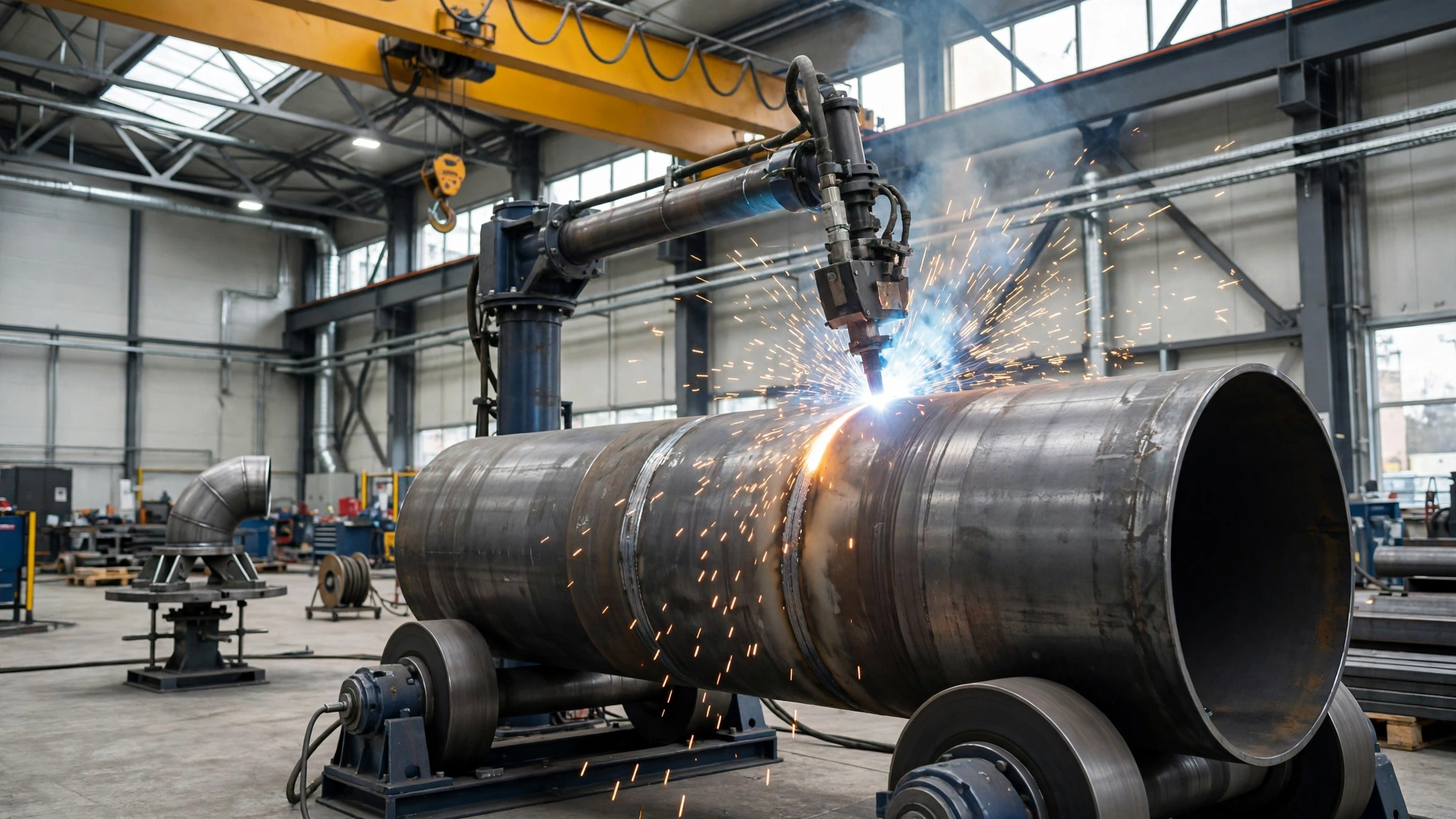
A straight spool, an elbow assembly and a small-bore stainless spool may all be called “pipe spools”, but they do not weld the same way, and they do not automate the same way. Buy the wrong route and the machine sits idle — or worse, it is used anyway, and the joints pay for it in repairs.
Short Answer
Let the pipe decide. If it is a supported cylinder that can turn freely, put it on a welding rotator and weld it flat. If it is an offset, flanged or branched assembly that must be gripped and reoriented, clamp it on a welding positioner and tilt each joint flat. If the pipe cannot move at all — already fitted, too long, or fixed in place — bring the welding head to the joint with an orbital system. That is the whole decision; the rest of this guide is about checking the pipe really fits the route, and what to do when the spool mix needs two routes.
The reason is weld position. A pipe rotating under a fixed torch is welded flat (1G): metal is deposited from above at constant travel speed. A fixed horizontal pipe is welded in 5G: flat at the top, vertical down the sides, overhead underneath, all in one joint. Converting a 5G joint into a 1G joint is a quality, rework and delivery decision.
MISA — MISA Welding & Cutting Automation, Wuxi, formerly Weld-Fab Automation — builds the first two routes directly: welding rotators and welding positioners, plus the column-and-boom manipulators that carry the torch over them. Orbital equipment is a third route shops commonly buy alongside them.
Why This Decision Costs More Than the Machine
A spool shop’s real costs are rarely the purchase price of one machine. They are the hours around the weld: crane waiting while a spool is flipped, re-rigging between joints, grinding out a repair, re-testing a failed joint, and the next job queuing behind an occupied bay. A rotator turning a 3-tonne spool smoothly can clear a week’s joints in a fraction of the manual time; the same rotator, given an elbow spool with its centre of gravity a metre off axis, will slip or stall.
Volume makes the gap wider: ten identical joints a week reward a repeatable setup, while two one-off joints a month do not. Every manual flip of a heavy spool is also a lift and a rigging operation; rotating it on rollers, or tilting a clamped assembly, keeps the load on the machine.
The Three Routes, in Plain Terms
The rotator route: the pipe turns, the torch stays still
A welding rotator — also called turning rolls — supports a cylindrical workpiece on a powered drive unit and an idler unit, and rotates it about its own axis at a controlled speed. The torch stays in one place, usually carried by a column-and-boom manipulator, and the joint passes under it. MISA rotators use friction-driven rotation with variable-frequency (VFD) speed control, in self-aligning configurations that adapt to different diameters without manual adjustment, and conventional adjustable configurations for heavier work. Wheels are polyurethane, rubber or steel to suit the surface; power can be configured from 110 V to 600 V, with wired or wireless pendant control.
The rotator’s strength is also its limit: it only rotates. It needs a cylinder — or a section cylindrical where the rollers touch it — and enough straight length for the drive and idler units to share the load. A spool with a flange at one end can work if the rollers sit on plain pipe; a spool with an elbow, branch or nozzle that hits the floor as it turns cannot.
MISA project examples: Gemlik, Turkey — 80-ton and 150-ton self-aligning rotators for 4,000–5,000 mm diameter foundation pipe; Rotterdam — a 50-ton fit-up growing line; Brisbane — a 20/40-ton growing line. See the welding rotator projects page.
The positioner route: the pipe is clamped, then tilted and turned
A welding positioner grips the workpiece — on a faceplate, in chuck jaws, or between a headstock and a tailstock — then rotates and tilts it, so each joint can be brought into the flat or horizontal position in turn. Where a rotator supports the pipe from underneath, a positioner holds it. That grip is the difference: a flanged spool, elbow assembly, valve body or branch connection can be clamped securely and reoriented without being unclamped between joints.
MISA builds positioners in tilting-turntable form (MWP series), manual-elevating form (MEWP, lift set by hand), hydraulic-elevating form (MHWP) and headstock–tailstock form for long parts. Published project material describes tilting of 0–120 degrees, rotation of 0–360 degrees and hydraulic lifting of 0–800 mm stroke on a 3-ton example, with capacities in older project material from 300 kg to 50,000 kg; final values are specified per project. In Dallas, a customer paired large rotators with a 5-ton positioner, using it to flip and rotate work at uniform speed with a chuck.
The positioner’s limit is its envelope: workpiece, fixture, chuck and counterweight must fit inside its rated load and centre-of-gravity envelope, and swing clear of the floor, base and torch through the full tilt range. An assembly too long, too offset, or too heavy on one side will overload the tilt drive or hit the floor. A headstock–tailstock set handles long parts better, but still needs a grip point at each end.
The orbital route: the pipe stays fixed, the head travels
Orbital welding turns the problem around: the pipe does not move. A head clamps around the pipe at the joint and rotates the electrode 360 degrees around it, under programmed control. TWI describes it as a mechanised gas tungsten arc (TIG/GTAW) process developed to remove operator error, with parameters set and stored by a computer so each weld repeats the last one. It is the standard joining method for high-integrity liquid and gas systems in semiconductor and pharmaceutical plants.
Orbital’s strength is repeatability on fixed pipe: the same stored program, travel speed and arc length, joint after joint, with parameters logged for traceability. Its limit is the head, which must clamp onto the pipe and fit around the joint with clearance to travel and withdraw. TWI notes orbital welding is more common on tubing than on larger pipe, because tubing gives the consistent outside diameters a head needs. Large-diameter, thick-wall pipe is usually a poor orbital job — the head gets big, the fill volume gets large, and a rotating-pipe process fills the joint faster.
The manipulator is not a fourth route
A column-and-boom welding manipulator moves the torch, not the workpiece: it raises, lowers and extends a boom over the joint, carrying a SAW, MIG/MAG or TIG head, synchronised with a rotator or positioner. The buying decision is therefore a cell — rotator plus manipulator, or positioner plus manipulator. Check stroke and control options on the welding manipulator page.
The Geometry-First Rule
Before any catalogue, sketch the spool and ask three questions in order. First, can the pipe be supported on rollers and turned about its own axis without anything hitting the floor or the machine? If yes, the rotator is the default. Second, if it cannot turn on rollers, can it be clamped and swung through its tilt range inside a positioner’s envelope? If yes, the positioner is the default. Third, if it can neither turn nor be clamped and swung, the joint must be welded where it sits, and orbital is the default.
This order prevents the most common expensive error: choosing the machine first and then discovering the pipe. A shop that buys a rotator because a neighbouring shop has one, then finds half its spools have elbows that foul the rollers, has bought a machine for the wrong half of its work.
The table below puts the three routes side by side. It is a decision aid, not a specification sheet: check every row against your own spool drawings. The machines look similar in a catalogue, and the differences that decide the purchase are the ones a catalogue hides — what moves, what shape it accepts, and what it cannot do. If a row eliminates a route, that route is out, however attractive its price.
| Route | What moves | Best pipe geometry | Typical joints | Best processes | Where it struggles |
|---|---|---|---|---|---|
| Rotator | Pipe rotates on rollers; torch stays still | Straight cylinder, plain pipe where rollers touch | Circumferential seams on straight spools, shells, vessels | SAW, MIG/MAG, TIG | Elbows, branches, offsets; non-cylindrical sections; very small diameters |
| Positioner | Clamped work rotates and tilts | Flanged, elbow, branch or offset assemblies that can be gripped | Circumferential, flange, branch and fillet joints, reoriented one by one | MIG/MAG, TIG, SAW | Long assemblies beyond the envelope; heavy offset loads; swing clearance |
| Orbital | Welding head orbits fixed pipe; pipe does not move | Fixed pipe or tubing with consistent outside diameter | Butt joints on fixed pipe, tube-to-tube, tube-to-fitting | Orbital GTAW/TIG, some orbital MIG | Large diameter, thick wall, high fill volume; tight head clearance; variable diameter |
The buyer conclusion: start with the “best pipe geometry” column, not the price column. A rotator wins on straight cylinders, a positioner on clamped assemblies, orbital on fixed pipe. If your spool appears in two rows, you have a two-route shop.
Five Measurements That Decide the Route
Diameter, wall thickness, weight, joint count and site constraints turn the geometry rule into a purchase. Get them from the spool drawings and the production plan, as ranges — smallest to largest — because a machine sized for the biggest spool and useless on the smallest is a common and expensive mistake.
Diameter sets wheel spacing, chuck and swing. Wall thickness sets process and fill volume: thin wall suits TIG and orbital GTAW, mid-range suits MIG/MAG, thick wall (12 mm and above) is where SAW earns its keep on rotating pipe — but SAW needs the flat position, which a rotator provides. Weight and centre of gravity set load and torque: a 20-tonne spool is not automatically a 20-tonne rotator job, because an offset flange moves the centre of gravity off axis. Joint count sets the payback; site constraints set what can be installed.
The table below maps each input to the signal it sends; use it at the quotation stage. It stops the conversation collapsing into one number: buyers who ask only “what tonnage?” get a tonnage answer, then discover diameter or floor space was the real constraint.
| Input | What to measure | Rotator signal | Positioner signal | Orbital signal |
|---|---|---|---|---|
| Diameter | Outside diameter range, smallest to largest (mm) | Inside the rotator’s diameter window; rollers contact plain pipe | Inside chuck / faceplate grip range; assembly swings clear | Inside the head’s clamp range; consistent outside diameter |
| Wall thickness | Wall thickness range (mm) | Thick wall favours SAW on rotating pipe | Any wall, if the joint can be tilted flat | Thin wall and small bore favour orbital GTAW |
| Weight and centre of gravity | Total weight (kg/t), centre of gravity, eccentricity (mm) | Load shared by drive and idler; torque covers eccentricity | Total clamped load inside the tilt and rotation envelope | Less critical; pipe is supported by its own structure |
| Joint count and volume | Joints per spool, spools per week, repeat orders | High repeat count of identical girth seams | Mixed joints on one clamped assembly | High count of identical fixed joints needing documentation |
| Site constraints | Floor area, swing height, crane capacity, power (V) | Floor length for drive + idler spacing; rail or trolley if needed | Swing clearance through full tilt; lifting height for loading | Head access and withdrawal clearance at every joint |
The buyer conclusion: five measurements, taken as ranges, decide the route before any quotation. Straight spools point to the rotator, offset spools to the positioner, fixed pipe with repeating joints to orbital. If two columns point at different routes, that is the two-route signal.
Worked Examples
Each example below is labelled as an example with stated assumptions. Substitute your own diameters, weights, rates and joint counts; the arithmetic is the reader’s, not a guarantee.
Example A — Straight large-diameter spool on a rotator with SAW
Assumptions: carbon steel spool, 1,200 mm outside diameter, 16 mm wall, 6 m long, about 3 tonnes, four circumferential joints per spool, six spools per week (24 joints per week). Process: SAW, torch on a manipulator, pipe on a self-aligning rotator. Labour and crane rate assumed at 60 currency units per hour — use your own rate.
Manual welding in 5G, with crane-assisted rolling, is assumed at 3 hours per joint including handling (72 hours a week). On the rotator, with the joint held flat, the same joint is assumed at 1.5 hours including loading and fit-up (36 hours a week) — saving 36 hours a week, or 2,160 per week at the assumed rate (about 112,000 over 52 weeks), before rework.
Example B — Flanged elbow spool on a positioner
Assumptions: carbon steel spool, 324 mm outside diameter, 10 mm wall, one 90-degree elbow, two flanges, about 450 kg including flanges and fixture, eight joints per spool, four spools per week. Process: MIG/MAG.
This spool cannot go on a rotator: the elbow swings below the pipe axis and would strike the floor, and the flanges put the centre of gravity off axis. On a positioner it is clamped in a chuck or bolted to a faceplate fixture, tilted so each joint faces up, and rotated at a steady speed. Assume manual handling takes 2 hours per spool and the positioner cuts that to 30 minutes, saving 1.5 hours per spool (6 hours a week). The positioner is bought here for access and quality, not labour saving.
Example C — Small-bore stainless spool, fixed pipe, orbital GTAW
Assumptions: 316L stainless steel tubing, 89 mm outside diameter, 3 mm wall, 40 identical butt joints per week, full penetration and a smooth internal bead required, parameters logged per joint. Process: orbital GTAW with an enclosed head, argon shielding and backing gas.
A rotator cannot hold 89 mm thin-wall tubing usefully, and a positioner adds clamping time to a small, identical joint. Assume manual TIG takes 25 minutes per joint and orbital takes 12 minutes including setup, saving 13 minutes per joint (about 8.7 hours a week at 40 joints) — plus documented repeatability manual TIG cannot offer. The key check is fit-up: the outside diameter must be consistent enough for the head to clamp, with straight clamping length and withdrawal clearance at every joint.
Together they show the rule working: straight heavy spool to the rotator, offset assembly to the positioner, small identical fixed joint to orbital.
When a Spool Shop Needs Two of the Three Routes
Most spool shops have a mix: straight runs, flanged elbow assemblies, and a small-bore stainless line. One route covers the bulk; the second covers the part the first cannot touch. Buying it is justified when the uncovered part is regular — a weekly elbow line, not a quarterly one-off — and when working around it costs more than the second cell.
The usual pairs are rotator plus positioner — straight spools and vessels on the rotator, flanged and offset assemblies on the positioner — and positioner plus orbital, for shops doing both structural spools and high-integrity small-bore work. Rotator plus orbital is less common, but happens in oil and gas fabrication.
Buy in order: buy the route covering the highest joint count first, run it for a quarter, and measure the joints it cannot take. That list is the specification for the second machine.
The table below maps common spool types to a first and second route. Find your spools in the first column; the second column tells you what to budget for next, if that type is a regular part of your work.
| Spool type | Example | First-choice route | Second route if volume grows |
|---|---|---|---|
| Straight pipe spool, large diameter | 1,000–2,000 mm diameter, 12–25 mm wall, girth seams | Rotator + manipulator (SAW) | Positioner for flanged ends and attachments |
| Straight pipe spool, mid diameter | 300–600 mm diameter, 6–12 mm wall, girth and flange joints | Rotator + manipulator (MIG/MAG) | Positioner for elbow and branch variants |
| Flanged elbow / branch spool | Elbow with flanges, branch connections, offset centre of gravity | Positioner (clamped, tilted) | Rotator for the straight runs in the same order |
| Vessel / tank shell section | Cylindrical shell, longitudinal and girth seams | Rotator + manipulator | Positioner for heads, nozzles and attachments |
| Small-bore stainless spool | 50–150 mm tubing, thin wall, many identical joints | Orbital GTAW | Positioner for flanged small assemblies |
| Long pipeline / foundation pipe | Multi-can pipe, grown section by section | Fit-up growing line + rotator | Positioner for end fittings and flanges |
The buyer conclusion: expect to own two routes once the mix is genuinely mixed, and plan floor space, power and crane access for the second cell from the start — even if it is bought a year later.
Process Pairing: Match the Process to the Position
Process and route must be chosen together, because the process sets the position it needs. SAW needs the flat position — the flux stays on the joint only with gravity helping — so it belongs on rotating pipe. MIG/MAG works in flat and horizontal positions, suiting both rotator and positioner work. TIG/GTAW is the precision process for thin wall, root passes and high-integrity joints, and in orbital form it is the fixed-pipe process. Running SAW on a fixed 5G joint, or orbital GTAW on a 25 mm wall girth seam, is a process error, not a machine error.
The table below pairs each process with the wall, diameter and movement it needs. Agree the process with the welding engineer before the machine is specified, not after it arrives.
| Process | Wall and diameter fit | Needs pipe to move? | Best route |
|---|---|---|---|
| SAW | Thick wall, about 12 mm and above; larger diameters (above about 200 mm for flux control) | Yes — joint must be flat while welding | Rotator + manipulator; positioner for clamped thick work |
| MIG/MAG (GMAW/FCAW) | Mid-range wall, about 3–20 mm; wide diameter range | Prefers rotation or tilt to flat/horizontal | Rotator or positioner + manipulator |
| TIG/GTAW, manual | Thin wall, about 1–6 mm; root passes; small to mid diameters | Prefers rotation, tolerates fixed pipe with skill | Rotator or positioner; manual on fixed pipe |
| Orbital GTAW | Thin wall tubing, small bore; consistent outside diameter | No — head orbits fixed pipe | Orbital head + power source |
| Orbital MIG | Mid-wall fixed pipe where fill is needed and head fits | No — head orbits fixed pipe | Orbital head + power source |
The buyer conclusion: lock process and route in the same decision. SAW needs a flat joint; orbital GTAW needs fixed pipe and a head that fits. Two processes usually mean two routes.
What Each Route Costs — and What It Saves
Purchase price is the least informative number here. The informative number is cost per finished joint: machine cost over its working life, plus labour, crane time, rework and floor space, divided by the joints it actually welds. A rotator welding 24 joints a week can cost less per joint than a cheaper machine welding four; an orbital system costing more per head can be cheapest on a 200-joint repeat order, because its setup is short and its repair rate is low.
The table below lists the main cost and time drivers for each route. It gives no prices — they depend on size, configuration and region. Fill in your joint count, labour and crane rates, and rework rate, and the route with the lowest cost per finished joint will show itself.
| Cost / time driver | Rotator | Positioner | Orbital |
|---|---|---|---|
| Purchase and installation | Drive + idler units, floor or rails, manipulator; moderate to high by tonnage | Machine, chuck / fixture, manipulator; moderate, rises with envelope | Power source, controller, heads and tooling |
| Setup per joint | Load and space the units; fast for repeat diameters | Clamp and fixture; slower per assembly, then fast joint-to-joint | Clamp head on pipe; fast once the program is stored |
| Arc-on and cycle time | High on repeat girth seams; steady speed | High once clamped; tilt between joints without unclamping | High on repeat identical joints; no operator variation |
| Labour and crane | Low after loading; one operator can run the cell | Low; loading is the crane job, tilting is the machine’s | Low; head is carried to the joint |
| Rework and inspection | Low on flat SAW/MIG joints; steady bead | Low on reoriented joints; overhead work removed | Low on repeat joints; logged parameters support inspection |
| Floor and power | Floor length for unit spacing; 110–600 V | Swing clearance and floor area through full tilt | Small footprint; power and gas at the joint |
The buyer conclusion: cost the route per finished joint over a year of your own joint counts. If the joint count is low, manual welding with good fit-up is often cheapest — a legitimate conclusion, not a failure to automate.
When Not to Use Each Route
Each route has boundaries, and knowing them keeps a purchase from becoming a regret.
Do not use a rotator when the spool is not cylindrical where the rollers touch it, when an elbow, branch or nozzle swings below the roller line, when the centre of gravity is far off axis and the drive cannot hold the load, or when the pipe is too small for the rollers to grip. Do not use it for a single longitudinal seam that needs the torch to travel — that is manipulator work.
Do not use a positioner when assembly plus fixture exceeds the rated load or centre-of-gravity envelope, when its swept circle hits the floor at full tilt, when there is no grip point — no flange face, pipe end for a chuck, or faceplate bolting — or when the assembly needs a headstock–tailstock set and only a turntable was quoted. A positioner that cannot swing is a very expensive table.
Do not use orbital when the diameter varies enough that the head cannot clamp, when there is no straight clamping length or clearance for the head to travel and withdraw, when the wall is thick and the fill volume makes orbital GTAW uneconomic, or when the pipe can be rotated — rotating the pipe is simpler, cheaper and faster than orbiting the head.
Do not automate at all — yet — when the joint count is very low, the spool mix changes every week, or the drawings are not settled. A manual welder with good fit-up will beat a cell that is re-set for every joint. Automation rewards repetition: buy it for the repetition you already have.
Common Buying Mistakes
- Choosing only by rated tonnage. A 20-tonne rotator does not automatically handle every 20-tonne spool. Diameter, centre of gravity, eccentricity and wheel contact decide whether the load turns smoothly or stalls mid-seam — a stopped weld, a repair, and a re-rigged spool.
- Buying a rotator for an offset or branched spool. The elbow or branch fouls the rollers or the floor, the centre of gravity fights the drive on every revolution, and the machine is abandoned for manual welding — capital spent with none of the benefit.
- Buying orbital for large-diameter, thick-wall work. A job SAW on a rotator would finish in a few passes takes many slow orbital passes, at a cost per joint no estimator can defend.
- Sizing by the largest pipe and ignoring the smallest. A rotator specified for 2,000 mm pipe may not grip a 300 mm spool, and an orbital head bought for one diameter cannot clamp another — leaving the everyday jobs uncovered.
- Ignoring swing clearance and floor space on a positioner. The assembly fits on the table but its swept circle hits the floor at full tilt, so the tilt range paid for cannot be used and joints meant to be welded flat are welded overhead instead.
- Ignoring the position limits of SAW. SAW needs the flat position so the flux stays on the joint. Specifying it for fixed 5G pipe, or pipe below about 200 mm diameter, produces poor beads and failed inspection.
- Buying one route for a two-route mix. The shop automates its straight spools, then discovers its elbow and flange work still goes manual, with all the crane waiting and rework automation was meant to remove — and the second machine is bought in a hurry, at a worse price, with no floor space left.
- Ordering without a joint list, drawings or production target. The supplier sizes from tonnage and diameter, the machine arrives, and the first real spool has a joint type nobody mentioned. The cost is the fixture, the rework, and the weeks lost ordering the correct configuration.
Buyer Checklist
- What is the outside diameter range and the wall thickness range? Diameter sets wheel spacing, chuck and head clamp range; wall sets the process. A range, not a single size, is what the machine must cover.
- What is the total weight, centre of gravity and eccentricity of each spool type, including flanges and fixtures? Weight alone does not size a machine; centre of gravity sets torque and tipping risk, and eccentricity decides whether the drive can turn the load.
- What joints does each spool have — circumferential, longitudinal, flange, branch — and in what positions? Girth seams favour rotation, mixed joints favour clamping and tilting, fixed butt joints favour orbital.
- Can the pipe turn on rollers, be clamped and swung, or must it stay fixed? Answer this from the spool drawing before any model is discussed.
- What weld process and code apply — SAW, MIG/MAG, TIG, orbital GTAW — and to which standard? The process sets the position the joint needs, and the code sets the inspection and documentation the cell must support.
- How many joints and spools per week, and how repeatable is the work? Volume decides whether automation pays, and which route pays first. A repeat order justifies a stored program; a one-off does not.
- What is the floor space, swing clearance, crane capacity and loading method? A machine that cannot be loaded, swung or reached in your bay cannot be used, however good its specification looks.
- What power supply and voltage are available? MISA rotators can be configured from 110 V to 600 V, but the configuration must be specified for the site.
- What control and synchronisation are needed — pendant, wireless, foot switch, PLC, rotator plus manipulator? Synchronised rotation and torch travel make a cell, rather than two machines standing next to each other.
- What inspection and documentation must each joint carry? Orbital’s logged parameters, a rotator’s steady bead and a positioner’s flat joints all help inspection — but only if stated before the cell is specified.
What to Send for a Quote
A useful quotation starts with the spool, not the machine. Send MISA: workpiece dimensions (diameter range, length, wall thickness per spool type); weight and centre of gravity, including flanges, fittings and fixture; joint type and a joint list per spool, with weld positions; weld process and the code or standard; production target (spools and joints per week, and repeatability); and facility constraints (floor space, swing height, crane capacity, power supply and voltage, loading method). Add a sketch of the most difficult spool — the elbow, offset flange or tightest access — because that spool sizes the machine.
Final Recommendation
Start with the pipe. Sketch the spool, check whether it can turn, be clamped, or must stay fixed, and let that answer choose the route. Size the machine from diameter range, weight, centre of gravity and joint list — not tonnage alone — and pair the process with the position it needs. Buy the route covering the most joints first, measure what it cannot take, and let that list specify the second route. Send the spool data to MISA and ask them to confirm the route before you order; the most expensive machine here is the one bought for the wrong pipe.
Sources
- TWI, “What is Orbital Welding?” — mechanised GTAW, repeatability, high-integrity applications. https://www.twi-global.com/technical-knowledge/faqs/what-is-orbital-welding
- Westermans, “Positioner vs Rotator vs Column & Boom: Which Do You Need?” — the three machines compared by what moves. https://www.westermans.com/knowledgehub/positioning-equipment-compared.aspx
- Canadian Metalworking, “Is submerged arc welding the right process for you?” — SAW, flat-position limit, below-200 mm diameter caution. https://www.canadianmetalworking.com/canadianfabricatingandwelding/article/welding/is-submerged-arc-welding-the-right-process-for-you-
- MISA, “Welding Rotator” — configurations, VFD control, wheel materials, voltages, pendant and trolley options. https://weld-fab.com/welding-rotator/
- MISA, “Welding Rotator Projects” — Rotterdam, Gemlik, Brisbane and Dallas projects. https://weld-fab.com/welding-rotator-projects/
- MISA, “Welding Manipulator” — column-and-boom stroke, processes and control options. https://weld-fab.com/welding-manipulator-2/
- ASME Section IX / AWS D1.1 welding positions (1G rotated pipe, 2G, 5G fixed pipe, 6G); confirm the applicable edition with your welding engineer.