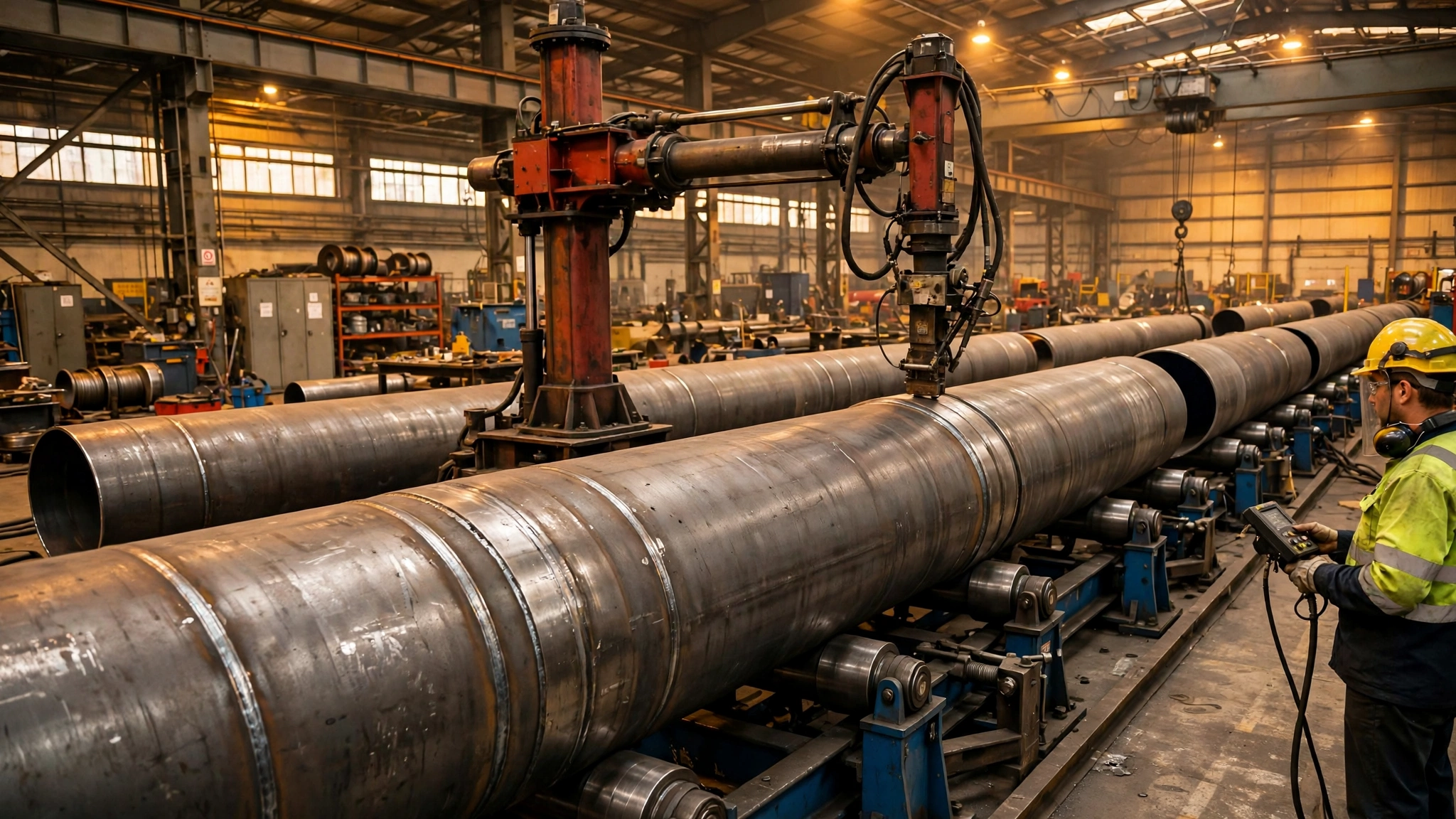
A long pipe is rarely made in one piece. It is built can by can: a rolled steel cylinder, typically 2 to 3 metres long, is joined to the next can, then the next, until the section reaches 12, 15 or 20 metres or more. Each joint is a full circumferential butt weld, and each one has to be round, straight and true, because the finished section must join the next section on site, often after coating.
That is the job a fit-up pipe growing line does. It is not simply a set of turning rolls. It aligns one can to the next, holds the joint while it is tacked and welded, then advances the growing assembly so another can can be added. If you make foundation pipes, wind tower sections, pressure vessel shells or long pipeline spools, this machine decides whether your circumferential welds pass inspection first time.
Short Answer
A fit-up pipe growing line is a line of drive and idler rotator sets fitted with hydraulic fit-up rollers. The rollers adjust the incoming can vertically, horizontally and axially until its end matches the can already on the line: same centre-line, same roundness at the joint, and the correct root gap all the way around. The two cans are tacked, the joint is rotated as one body under a stationary welding head — normally submerged arc welding (SAW) for the fill passes — and the longer assembly is moved along the line so the next can can be fitted.
MISA’s lines are the MCF and MSAF series. On MISA’s published product pages, both share the same core construction: an all-fabricated-steel base, wheel brackets manually positioned to suit different diameters around a constant centre-line, a two-motor, two-wheel-drive system, inverter-controlled AC drive motors, and two hydraulic rollers driven by a pump station. The published examples are the MCF-40, listed at 40 tonnes with a 500 to 4,200 mm diameter range, and the MSAF-20, listed at 20 tonnes with a 500 to 4,200 mm range (confirmed by MISA 2026-11-15; the product page title says 500 to 3,500 mm, which is wrong). Those figures are supplier claims, and final values are specified per project by MISA engineers.
Buy a growing line when alignment is your bottleneck, not rotation. If your cans are round and joints are few, a rotator set alone may be enough. If you join can after can and every joint needs correcting, a growing line removes that correction from the critical path.
Why Fit-Up, Not Welding Speed, Is Usually the Bottleneck
The arc is rarely the slow part. SAW deposits metal fast, and a manipulator can hold a welding head steady for a full circumference. What slows a shop is everything before the arc starts: getting the next can onto the line, meeting the previous can, checking gap and step, correcting out-of-roundness, tacking and re-checking.
Rolled cans are never perfectly round. Plate thickness varies, rolling leaves a flat at the seam, and handling ovalises the ends. At the joint that shows up as hi-lo: a step between the outside surfaces of the two cans. A step beyond your welding procedure limit is a lack-of-fusion risk at the root — exactly what ultrasonic or radiographic inspection finds. The repair is gouging out completed weld and re-welding it, with re-inspection, while the line stands idle.
The root gap behaves the same way: too wide, the root pass burns through; closed up, it does not penetrate. A mechanised SAW head cannot see the pool — the arc is buried under flux — so it depends entirely on the joint being right before welding starts. That is why TWI describes SAW as ideally suited to longitudinal and circumferential butt welds, normally done in the flat position, with the flux and molten pool at the top of the pipe while the pipe turns underneath.
A growing line attacks this at its source. Instead of fitting up with jacks, wedges and crane nudges, the operator adjusts the can on powered hydraulic rollers and measures the result. The correction is repeatable because the machine, not the operator’s judgement, makes the adjustment. It also keeps the assembly on a fixed centre-line, so the flange at the far end lands where the drawing says it should.
How a Growing Line Works, Step by Step
1. Load the first can. It is craned onto the drive and idler rotator sets and centred, with wheel brackets set to its diameter so it sits on a constant centre-line.
2. Bring in the next can. It is loaded onto the fit-up rollers at the loading end, millimetres apart in height, sideways offset, and axially gapped from the first can.
3. Align in three directions. Hydraulic cylinders move the incoming can vertically, horizontally and axially (next section). The operator checks hi-lo and root gap around the circumference, and adjusts until both are within the welding procedure limits. Out-of-roundness is corrected locally, where the tolerance is measured.
4. Tack the joint. With the joint held by the hydraulic rollers, the cans are tack welded at intervals around the circumference. The tacks must hold alignment while the assembly rotates, and they are part of the weld — a cracked tack becomes a defect in the finished joint.
5. Weld the root, then the SAW fill and cap. The root is the most demanding pass. Then a column-and-boom welding manipulator carries the SAW head to the top of the joint, in the flat position, and the pipe rotates beneath it. Thick walls need several passes, with slag cleaning between passes.
6. Advance and repeat. Once the joint is complete and inspected, the assembly is moved along the line so the free end is back at the fit-up station, and the cycle repeats. The pipe “grows” one can at a time until the section is complete, then it is lifted off. Output is measured in finished sections per shift.
The Three Hydraulic Adjustments, Explained
Vertical adjustment raises or lowers the incoming can, correcting a difference in centre height and sag, where a long can’s free end droops between supports. Horizontal adjustment moves the can sideways, correcting a lateral offset from a can craned in off-axis or a previous can that is not straight; a few millimetres is enough to put the root gap out of tolerance on one side. Axial adjustment moves the can along the pipe axis and sets the root gap — the adjustment operators reach for most, because the gap is easiest to measure. But axial adjustment alone cannot fix hi-lo: pushing two out-of-round ends together closes the gap on the high side and leaves a step.
The three adjustments work together, under load, while the can sits on the rollers. The operator does not lift the can off, shim it, and put it back to try again. Minutes per joint, repeated dozens of times a week, is where the time goes.
Ask MISA for the vertical, horizontal and axial travel for your diameter range — no hydraulic stroke is published for the MCF or MSAF series — and check it against the worst out-of-roundness your cans actually have. Also ask how the rollers hold the adjustment while the joint rotates, and what happens on power loss.
Why SAW, and Why the Pipe Has to Turn
In SAW, the arc burns between a continuously fed wire electrode and the workpiece, completely covered by granular flux, which shields the weld pool, forms a slag covering, and can add alloying elements. No shielding gas is needed. Because the arc is buried, there is almost no spatter or visible arc light — but the operator cannot see the weld pool. As TWI puts it, great reliance must be placed on parameter setting and filler-wire positioning: SAW rewards a good joint and punishes a bad one.
SAW must also be welded in the flat position for butt joints. The weld pool and molten slag are highly fluid; tilt the joint and the flux runs off and the weld collapses. So the welding head sits at the top of the pipe, at 12 o’clock, and the pipe rotates beneath it. Rotation speed sets travel speed, so it must be smooth and repeatable — jerky rotation shows up as an uneven bead. Hence MISA’s two-motor, two-wheel-drive arrangement with inverter-controlled AC motors, and the need for drive and idler sets to stay synchronised as the assembly grows heavier.
The root pass deserves separate attention. SAW is excellent for fill and cap passes, but the root — the first pass, which must fuse the very bottom of the joint — is often made by another process, or by SAW from the inside. MISA’s application notes say a growing line is applicable to inner and outer ring seams, so specify internal access if your procedure needs it. If it calls for an internal root, say so in the RFQ; it changes the line layout, access, and manipulator.
Growing Line, Rotator Set or Manual Fit-Up: Choosing the Route
The choice is about which constraint limits your output. If your constraint is rotation — a short vessel needing turning under a welding head — a rotator set is enough. If your constraint is fitting up the next joint, time after time, rotation alone does not help, and the growing line addresses the actual bottleneck.
| Approach | Fit-up control | Weld quality repeatability | Best for | Main limitation |
|---|---|---|---|---|
| Manual fit-up with crane and jacks | Operator, jacks and wedges; no powered adjustment | Low; depends on operator and joint | One-off joints, short runs, irregular work | Slow; hi-lo and gap vary; crane tied up |
| Rotator set alone | Rotation only; alignment done before loading | Medium; good once joint is tacked true | Single cans, short vessels, few seams | Cannot correct hi-lo or root gap after loading |
| Fit-up pipe growing line | Powered vertical, horizontal and axial adjustment under load | High; joint set and held before welding | Long multi-can pipes, wind tower sections, foundation pipes in volume | Needs floor length, crane access, matched manipulator |
Do not buy a growing line because it looks more capable than a rotator set. Buy it when you can point to a repeated fit-up problem — joints needing rework, sections running late, or inspection failures at the root — that repeats often enough to pay for the line. If you weld only a few circumferential seams a week, a good welding rotator and a manipulator are the cheaper answer. If you weld the same joint five times a day, the growing line is the pacing machine for the whole shop.
MCF vs MSAF: What Is Published, and What to Confirm
A buyer searching for the difference between MISA’s MCF and MSAF series will find two product families, both described as fit-up pipe growing lines, with pages sharing the same base description almost word for word. The pages publish no clear technical distinction. Inventing one would send a buyer to order the wrong series for a reason that does not exist. The table below therefore separates what MISA publishes for each named model from what the buyer must confirm before ordering.
| Feature | MCF-40 (published) | MSAF-20 (published) | Confirm before ordering |
|---|---|---|---|
| Safe working load, drive/idler set | 40 t | 20 t | Load at heaviest intermediate stage, not just finished assembly |
| Vessel diameter range | 500–4,200 mm | 500–4,200 mm (confirmed by MISA 2026-11-15; page title says 500–3,500 mm) | Confirm the range in writing for the model quoted |
| Base and wheel brackets | All-fabricated-steel base; brackets manually positioned around constant centre-line | Same published description | Bracket setting time when diameter changes often |
| Drive system | Two-motor, two-wheel-drive; inverter-controlled VFD AC motors; no torque tube | Same published description | Rotation speed range; synchronisation |
| Hydraulic rollers | 2 hydraulic rollers, pump station; hydraulic lifting | 2 hydraulic rollers, pump station; hydraulic lifting | Vertical, horizontal, axial travel (mm) |
| Wheels | Polyurethane wheels | Polyurethane wheels; automatic roller-spacing adjustment listed | Wheel material and spacing for your wall thickness |
| Control and certification | Wired remote; wireless optional; CE / UKCA / CSA / SGS listed | Wired remote; wireless optional; CE / UKCA / CSA / SGS listed | Which certification applies to your country |
Size by the job, not by the series letter. Choose capacity from the heaviest load the line will actually carry — which may be an intermediate stage, not the finished pipe — and diameter range from the smallest and largest cans you will run. Then ask MISA, in writing, which model they propose and what the hydraulic travel is. MISA’s project history also lists larger lines than either published model: Rotterdam was 50 tonnes, Brisbane 20/40 tonnes. Treat the published models as a starting point, not the full range.
Where a Growing Line Fits: Application Matrix
A growing line earns its keep where the same circumferential joint repeats many times along a long assembly. Where joints are few, diameters change constantly, or the workpiece is not cylindrical, it is the wrong tool.
| Application | Typical diameter and length | Joint and process | Recommended route |
|---|---|---|---|
| Foundation pipes | 2,000–5,000 mm diameter; sections 12–30 m | Circumferential butt, SAW fill; often 100% inspected | Growing line + manipulator; Rotterdam and Brisbane cases |
| Wind tower sections (can stacks) | 2,400–4,600 mm diameter; cans about 2.7 m; sections 12–30 m | Circumferential butt, SAW; full penetration; roundness critical for site bolting | Growing line + manipulator; fit-up is the pacing station |
| Long pipeline spools / line pipe | 500–2,000 mm diameter; long multi-can assemblies | Circumferential butt, SAW or MIG root + SAW fill | Growing line for volume; rotator set for short spools |
| Pressure vessel shells | 1,000–4,200 mm diameter; shells 3–12 m | Circumferential and longitudinal butt, SAW | Rotator set + manipulator; growing line if many repeat |
| Short tanks, single cans, job-shop vessels | Wide diameter range; one or two seams per vessel | Circumferential butt, SAW or MIG | Rotator set alone; growing line is over-specified |
| Non-cylindrical, offset or heavy-flange work | Irregular geometry; eccentric centre of gravity | Varied joints and positions | Positioner or headstock-tailstock system, not a growing line |
Length and repetition, not diameter alone, decide the case. A 4-metre-diameter vessel with two seams does not need a growing line; a 2-metre-diameter foundation pipe with ten seams does. Count your circumferential joints per week, and how many need rework. Those two numbers tell you whether the line will pay.
The Tolerances That Decide Pass or Fail
A growing line is a tolerance machine: its value is holding a joint inside the limits your welding procedure and inspection standard allow. The figures below are typical values from code summaries — millimetres, not centimetres — and the governing code and your qualified WPS set the actual limit for your job.
| Tolerance | What it controls | Typical limit (check your code / WPS) | Consequence if missed |
|---|---|---|---|
| Hi-lo (radial mismatch) | Step between the two can surfaces at the joint | About 10% of thinner wall thickness or 3 mm, whichever is smaller (AWS D1.1); API 5L about 10%, max. 1.6 mm | Lack of sidewall fusion at the root; UT/RT failure; gouge and re-weld |
| Root gap | Consistency of the gap around the circumference | Typically 1–4 mm depending on process and joint design | Burn-through where gap opens; lack of penetration where it closes |
| Roundness / ovality at the joint | Whether the finished section accepts the next can or flange | Set by project specification; measured in mm over metres of diameter | Flange will not bolt up on site; the most expensive failure, after coating |
| Axial alignment / straightness | Whether the growing assembly stays on its centre-line | Set by project specification; check over the full section length | Cumulative drift; finished section is out of straightness and will not fit |
| Longitudinal seam offset | Position of longitudinal seams relative to each other | Commonly offset by at least 150 mm at a circumferential joint | Seams crossing at a joint create a stress concentration and inspection problem |
Write the tolerances into the RFQ. A supplier told “hi-lo to 10% of wall thickness, max. 3 mm” can propose a machine and a measurement method. A supplier told only “we weld pipes” cannot. And a shop that does not measure hi-lo and root gap at every joint will not get the benefit of a growing line — the machine can hold the tolerance, but only the operator can verify it.
MISA Project Evidence: Rotterdam and Brisbane
This section rests on what weld-fab.com publishes on its welding rotator projects page, read for this article. Both examples are supplier-published project notes; delivery times, warranties and performance descriptions are MISA’s claims, not independently verified facts. They show MISA has supplied lines of this size — they do not guarantee the same size will fit your shop.
Rotterdam, Netherlands — 50-tonne fit-up growing line, October 2019. The customer produces foundation pipelines and was preparing a new project. MISA supplied two sets of 50-tonne fit-up growing line, delivered in 25 days according to the note, with two engineers installing and debugging it in two days. A 13-month warranty and lifetime technical support are stated. The line is described as “mainly used for the assembly and welding of pipelines” and “often suitable for the production of wind power equipment or the welding of foundation pipes.”
Brisbane, Australia — 20/40-tonne fit-up pipe growing line, April 2019. The customer is a steel manufacturer producing pipes and wind towers, on an infrastructure project needing large quantities of foundation pipelines on a tight schedule. MISA supplied a 20/40-tonne line, with a customised LH5090 welding manipulator and a CNC plasma cutting machine. The note says the customer required 24-hour uninterrupted operation, and MISA selected reducers, motors and controls rated for continuous running; a 24-month warranty is stated, and delivery as 35 days. Two points matter. First, the growing line alone did not complete the job: it was bought with the manipulator that does the welding. Second, the 24-hour duty cycle was specified up front and drove component selection. If your line will run around the clock, say so.
Floor, Rails, Crane and Power: The Requirements Buyers Forget
A growing line is long — the requirement most often underestimated. It must hold the finished assembly at full length, plus the loading end, manipulator travel, and crane access. A 20-metre section does not fit in a 20-metre bay. Each row below is something the supplier needs to know or the buyer needs to check, and the third column says what goes wrong if it is missing.
| Item to send or check | Why the supplier needs it | What goes wrong without it |
|---|---|---|
| Finished section length and max. assembly weight | Sets line length, number of sets and capacity | Line too short; assembly overhangs or cannot be supported |
| Diameter range, smallest to largest can | Sets wheel bracket range and roller spacing | Small cans do not sit stably; large cans exceed the range |
| Can length, wall thickness, material | Sets fit-up load, wheel contact and welding procedure | Wheels mark thin cans; heavy cans overload the hydraulic rollers |
| Floor load capacity and levelness | Line plus assembly is a concentrated load on the slab | Floor cracks or settles; centre-line drifts |
| Rail requirement (fixed vs travelling sets) | Travelling sets need rails, foundations and power feed | Line cannot advance the assembly; crane becomes the bottleneck |
| Crane capacity, hook height and bay span | Loading a can and lifting off a finished section needs both | Finished section cannot be lifted off |
| Power supply: voltage, phases, available current | Drive motors, pump station and manipulator all draw power | Line trips the supply; SAW and hydraulics cannot run together |
| Manipulator stroke, reach and travel | SAW head must reach every joint along the full section | Far-end joints cannot be welded without repositioning |
| Duty cycle: shifts per day, sections per week | Continuous running changes motors, reducers and cooling | Equipment overheats or fails early on 24-hour running |
| Safety: guarding, e-stop, access and training | Rotating multi-tonne assemblies are a serious hazard | Operators work unguarded around a rotating load |
Measure the shop before ordering. The cheapest growing line fits the building you already have; the most expensive arrives needing a new floor, crane or power supply. Send the supplier a sketch of the bay with dimensions, crane data and power data, and ask them to confirm the layout in writing.
Two Worked Examples (Labelled Examples with Stated Assumptions)
Example 1 — Cycle time. Assume a shop assembles 15 m foundation pipe sections from 2.5 m cans: six cans, five joints per section. Assume manual fit-up takes 90 minutes per joint and a growing line 30 minutes — assumptions, not MISA data; substitute your own times. The saving is 60 minutes × 5 joints = 5 hours per section, or 20 hours per week at 4 sections per week. Multiply by your own labour and crane rate to test the case. If your manual fit-up already takes 30 minutes, the line will not save 5 hours — measure before you buy.
Example 2 — Weight as the assembly grows. Assume a 20-tonne line and 3-tonne cans. The finished 15 m section weighs 18 tonnes, inside the rating — but that is not the whole check. At an intermediate stage, supported on fewer sets or with a long overhang beyond the last support, the load on one drive/idler set can exceed the finished average. Check the load at the heaviest intermediate stage, with the longest overhang, and ask MISA to confirm it.
When Not to Use a Growing Line
Do not buy one for one-off or very short-run work. If you weld a handful of seams a month, a rotator set and a manipulator will do the job at a fraction of the cost.
Do not buy one for non-cylindrical work. Square sections, heavy offset flanges, eccentric assemblies and workpieces that need tilting belong on a positioner or headstock-tailstock system, not on a growing line.
Do not buy one if your cans vary wildly in diameter and you have no time to reset the line. The MCF/MSAF wheel brackets are manually positioned — fine when diameter changes weekly, a burden when it changes three times a day.
Do not buy one if you cannot feed it. A growing line needs a steady supply of prepared cans — cut, bevelled, rolled and checked — on schedule. If can preparation is the bottleneck, the money should go there first.
Do not buy one without the welding side. A line that fits up beautifully then waits for a manual welder, or a manipulator that cannot reach the joint, has solved half the problem. Brisbane is the model: line, manipulator and cutting were bought as a system. If your budget only covers the line, wait until it covers the system.
Common Buying Mistakes
- Buying by rated tonnage only. A 20-tonne line does not automatically handle every 20-tonne assembly safely. Diameter, centre of gravity, eccentricity and wheel contact can make the same weight unsafe — causing slipping, stalling, or a tipping risk.
- Assuming MCF and MSAF differ in a way MISA does not publish. The published pages share the same base description. Ordering on an assumed difference can leave you with the wrong capacity or diameter range, and a specification you cannot hold the supplier to.
- Sizing for the first can, not the finished growing assembly. Load, length and centre of gravity all change as cans are added. A line sized for one can can be overloaded, too short, or unstable by the fourth joint — forcing a crane lift mid-job.
- Ignoring out-of-roundness and hi-lo at the joint. If your cans arrive oval and you have no measurement routine, the hydraulic adjustment will not be used properly — giving the same inspection failures as before, on a more expensive machine.
- Buying the line without the manipulator, root process or internal welding access it needs. The line aligns and rotates; it does not weld. Without a manipulator that reaches every joint and a root method that suits your procedure, it becomes a very expensive fit-up table.
- Ignoring floor, rails, crane and power until delivery. A line that does not fit the bay, cannot be lifted by the crane, or trips the power supply is not a bargain at any price. A new floor or crane upgrade can exceed the cost of the line.
- Ordering without a drawing, joint list, tolerance and production target. The supplier cannot size a line from “we weld pipes.” Without drawings and a production target, the quotation is a guess, and the machine that arrives is the supplier’s guess, not your specification.
Buyer Checklist
- What is the diameter range, can length, wall thickness and material? Diameter sets the bracket range, length sets support spacing, thickness sets wheel contact and the procedure. Without all four, the line cannot be sized.
- What is the weight per can, and the weight and centre of gravity of the finished assembly? They set the load on each rotator set, the torque to turn it, and the tipping risk as it grows.
- What are the joint types, and what hi-lo, root gap and roundness does your WPS and code allow? The tolerance decides whether the hydraulic adjustment is good enough. If the line cannot achieve it, it cannot deliver your weld quality, whatever its tonnage.
- What is the weld process, and how is the root pass made? SAW fill, MIG root, internal and external root all change the line layout, manipulator and access. The root method is most often left out of the RFQ, and causes the most rework.
- What is the production target — sections per week, shifts per day, and duty cycle? A line running one shift a week and one running 24 hours a day, as in Brisbane, need different motors, reducers and cooling. Duty cycle drives price.
- What manipulator stroke, reach and travel do you need? The SAW head must reach every joint along the full finished length. One that is too short forces repositioning, breaking the line’s rhythm and risking alignment.
- What are the floor load, levelness, rail, crane and power constraints? The line is only as good as the building it stands in. Floor, crane and power limits are the most common reason a delivered line cannot be installed as planned.
- What control do you want — wired pendant, wireless pendant, PLC, or synchronisation with the manipulator? Control affects safety and operator position. Confirm wireless range for your bay size.
- What safety, certification and documentation do you need? CE marking, local safety rules, guarding, emergency stop and hydraulic holding on power loss all need specifying. MISA lists CE / UKCA / CSA / SGS; confirm which applies to your country.
- What installation, commissioning, training, spares and warranty are included? The Rotterdam and Brisbane notes both mention engineers travelling to install and debug the equipment. Confirm who does that, how long it takes, and what training and warranty cover.
What to Send for a Quote
Send MISA — or any growing-line supplier — a short RFQ pack, not a one-line enquiry. Include: workpiece dimensions and diameter range; can length, wall thickness and material; weight per can and for the finished assembly, with centre of gravity; joint type, bevel and tolerances (hi-lo, root gap, roundness); weld process and root method, and whether internal welding is needed; production target (sections per week, shifts per day, duty cycle); manipulator requirements (stroke, reach, travel, SAW equipment); power supply (voltage, phases, available current); facility constraints (floor plan, floor load, rails, crane capacity and hook height, bay length); and delivery, installation, commissioning and training needs.
Final Recommendation
A fit-up pipe growing line is a good investment when you make long, multi-can pipes in volume and fit-up time and inspection failures limit output. It aligns, holds and rotates the joint so a mechanised SAW head can do its best work, and keeps the assembly straight so the finished section fits on site. It is a poor investment when your work is one-off, non-cylindrical, or short-run, or when your shop cannot feed, power or lift from it.
If that fits your work, measure your cans, joints and shop, write down your tolerances and production target, and send the RFQ pack above to MISA. Ask them, in writing, which model they propose and what the hydraulic travel is.
Sources
- MISA / Weld-Fab, Welding Rotator Projects — Rotterdam 50-tonne and Brisbane 20/40-tonne fit-up growing lines (weld-fab.com/welding-rotator-projects/, read 2026-11-14). Delivery times and warranties in those notes are supplier claims.
- MISA, MSAF-20 product page (misamfg.com, read 2026-11-14): 20 t safe working load, 500–4,200 mm diameter range — confirmed by MISA 2026-11-15 (the page title says 500–3,500 mm, which is wrong); two-motor drive, hydraulic rollers, CE / UKCA / CSA / SGS.
- MISA, MCF-40 product page (misamfg.com, read 2026-11-14): 40 t safe working load, 500–4,200 mm diameter range, same base description as MSAF-20.
- TWI, Equipment for Submerged Arc Welding: https://www.twi-global.com/technical-knowledge/job-knowledge/equipment-for-submerged-arc-welding-016
- TWI, What is Pipe Welding?: https://www.twi-global.com/technical-knowledge/faqs/what-is-pipe-welding
- Redrock Automation, Fit Up Bed and Growing Line System: https://redrockautomation.com/fit-up-bed-growing-line-systems/
- AWS D1.1 and API 5L: fit-up tolerance principles; the reader’s own WPS and governing code govern. MISA background: MISA — About Us.