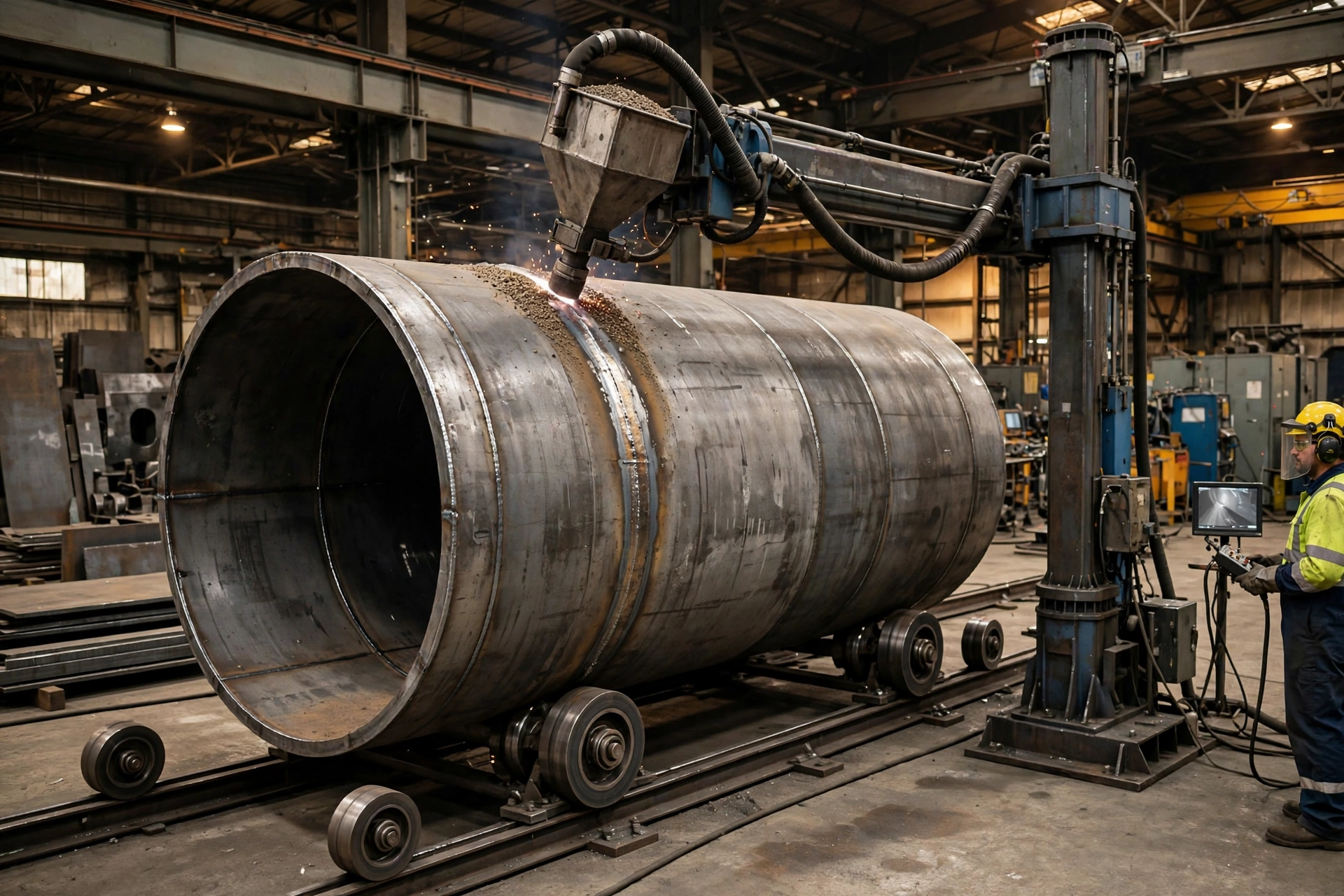
A wind tower section looks simple: a big steel tube. The welding is not. Each section is built from several rolled steel cans, each can closed by a longitudinal seam, each can joined to the next by a circumferential seam, and the section finished with flange welds that must bolt up cleanly on site, sometimes 80 m to 120 m in the air. Those circumferential seams carry fatigue load for 20 to 30 years. A weld that looks acceptable but fails ultrasonic testing (UT) does not just cost a repair — it stops the section, ties up the crane, and pushes the delivery date.
Most serious tower fabricators therefore build a cell: welding rotators that turn the section at a steady surface speed, a column-and-boom manipulator that holds the submerged arc welding (SAW) head over the seam, and a travel trolley that moves the work or the manipulator to the next joint. This article explains how that cell works, how to size it, what it costs, when not to build it, and what to send MISA for a quotation.
Short Answer
For large-diameter, heavy tower sections welded in repeat production, build a self-aligning rotator set plus a column-and-boom SAW manipulator on a powered travel trolley, with anti-drift control and seam tracking. The rotators turn the section so the circumferential seam stays in the flat position under a stationary torch; the manipulator supplies the reach, height and flux handling to keep the arc on the joint for the full circumference; the trolley moves the cell to the next seam without a crane lift.
That is the right answer when three conditions are all true: the sections are large and heavy enough that manual positioning wastes more time than the cell saves; the seam list repeats; and the shop can give the cell a level rail bed, enough floor loading, and enough crane capacity and hook height to load the heaviest section. If any of those fails — one-off sections, small diameters, a floor that cannot take the load, or fit-up so poor that no machine can hold the root — fix that problem first. A welding cell cannot fix a bad bevel, an out-of-round can, or a missing crane.
MISA builds this cell from equipment it already supplies for wind-tower and foundation-pipe work: MCR conventional and MSAR self-aligning welding rotators, column-and-boom welding manipulators with PLC synchronisation to the rotators, powered travel trolleys, and MCF/MSAF fit-up pipe growing lines where alignment, rather than welding speed, is the bottleneck. Project examples in this article are MISA supply examples, not guarantees — final sizing always comes from your section drawing.
Why This Topic Matters
Weld quality and rework. A circumferential seam welded at a wandering travel speed has wandering heat input, and heat input drives penetration, bead shape and, on thick plate, toughness. A rotator under variable-frequency drive (VFD) control holds surface speed steady, so the welding procedure specification (WPS) heat-input window is actually held, not just written down. Rework on a tower section is expensive, because the section must be rotated back, ground out, re-welded and re-inspected while the cell produces nothing. In the Aerisyn wind-tower plant described by The Fabricator, confidence in weld consistency allowed ultrasonic testing to be reduced from 100% of welds to 20%.
Cycle time and arc-on time. Arc-on time is the fraction of the shift when the arc is actually burning. Everything else — crane waiting, repositioning, tacking, flux handling — is time the cell is not welding. A rotator + manipulator cell attacks the non-welding time directly: the section stays in the cell while the torch moves to the joint and the trolley moves the work along the rails.
Labour, safety and crane waiting. Large-section welding at height, in awkward positions, for full shifts is fatiguing, and fatigue degrades quality late in a shift. In the cell the operator stands at a safe distance, watches the seam on a camera monitor, and adjusts parameters rather than holding a torch over a 4,000 mm diameter shell; MISA manipulators offer a wireless pendant with up to 300 ft (90 m) working radius. A rotating load of tens of tonnes is also a hazard if uncontrolled, so the cell needs matched drive torque, correct wheel material and spacing, end-stop rollers, anti-drift sensing and emergency stops. Every crane lift of a 20-tonne to 50-tonne section also needs a crane, a driver, riggers and a clear bay; a cell that grows a section can by can removes most of those lifts.
Technical Background
From plate to tower
Flat steel plate — commonly S355 grades in Europe, or ASTM A709 Grade 50 in North America — is cut, bevelled and rolled into a short cylinder called a can, typically around 2,400 mm to 3,000 mm long. Several cans are joined end to end to make a tower section, typically 20 m to 35 m long; an average section in the Aerisyn plant described by The Fabricator was 14 ft (about 4,267 mm) in diameter, 50 ft to 100 ft (15 m to 30 m) long, and weighed up to 50 tons. Several sections are then bolted together on site through end flanges to make a tower 80 m to 120 m tall onshore. Diameter falls toward the top, so many sections are slightly conical (tapered). Wall thickness grows toward the base: commonly 10 mm to 40 mm on onshore tower cans, and 40 mm to 150 mm on offshore monopiles.
The two seam families
Longitudinal seams close a single rolled can: one straight seam, typically 2,400 mm to 3,000 mm long. The can is held still and the torch travels along the seam, welded from the outside and usually also from the inside. Circumferential seams (girth seams) join can to can and can to flange. The seam runs around the full circumference — for a 4,000 mm diameter section, more than 12 m of weld in a single joint. The torch stays in one place and the section rotates beneath it. That is the rotator job, and the seam family this cell is built around.
Why SAW is the default process
Submerged arc welding (SAW) is the standard process for tower-can seams. The arc is struck between a continuously fed wire electrode and the workpiece under a blanket of granular flux, which generates the shielding gas and slag that protect the weld pool, adds alloying elements, and hides the arc completely — no visible arc light, little fume, almost no spatter. Because the arc is buried, heat loss is low and deposition rates are high, which is what thick plate needs. TWI guidance on SAW equipment lists the essentials: a power source, a SAW head, and flux handling. SAW is a high-current process — a single 4.0 mm diameter wire is commonly run at 600 A to 900 A, and a twin-wire system at 800 A to 1,200 A. Current, voltage and travel speed together set bead shape, penetration and heat input, and because the operator cannot see the weld pool under the flux, the process relies on correct parameter settings, stable travel speed and good joint preparation. Single-wire SAW is the baseline; twin-wire SAW can raise deposition by roughly 20% to 30%; tandem SAW uses two separate arcs for the highest deposition on thick plate. Specify the SAW variant in the RFQ: it changes the power source, head load, flux system and rotator speed range. Flux must be stored dry, fed ahead of the arc from a hopper, and unused flux recovered by vacuum after slag and metal dust are removed.
Quality framework
The cell does not set the quality standard; the project does — commonly AWS D1.1 in North America or EN 1090-2 / EN ISO 15614-1 / EN ISO 5817 in Europe, plus DNV-ST-0126 offshore. Those documents set the travel-speed window, heat input, preheat/interpass and NDT extent; confirm them before specifying equipment.
The Cell: Rotator + Manipulator + Trolley
A wind-tower welding cell has four functional parts, and the buyer should think of them as one system.
1. The rotators. A welding rotator set is a drive unit and an idler unit. The drive unit rotates the section through friction between motorised rollers and the shell surface; the idler unit supports the other end. MISA rotators are friction-driven with VFD speed control, so surface speed can be set finely and held steady. Wheel material is chosen for the shell surface: polyurethane (PU) wheels for coated surfaces and higher friction, rubber wheels for general use, or steel wheels — optionally knurled — where PU would not survive heat or load. Self-aligning rotators (MISA MSAR series) adjust automatically to the section diameter; conventional rotators (MISA MCR series) use adjustable wheel spacing and suit the heaviest, constant-diameter work. A 60-ton drive-and-idler set, the MSAR-60, is a MISA-published example with a 750 mm to 4,500 mm diameter range — a sizing reference, not a promise that 60 tonnes covers every 60-tonne section.
2. The manipulator. A column-and-boom welding manipulator is a rigid vertical column with a horizontal boom carrying the SAW head, wire feeder, flux hopper and often a camera. MISA manipulators come in light, heavy-duty, fixed and motorised moving (rail-travelling) types, with a typical published vertical stroke of 2 m to 6 m or more and horizontal stroke of 2 m to 8 m or more. Heavy-duty types are built for sustained high-amperage, multi-shift SAW with twin-wire heads and flux recovery — the type a tower cell normally needs. A cross-slide gives fine torch adjustment, and a rotation head allows rapid switchover between longitudinal and circumferential torch orientation.
3. The travel trolley and rails. Either the rotator set travels under a fixed manipulator, or the manipulator travels past a fixed rotator set, or both travel. Powered travel trolleys under the rotator base move the section along the rails to bring the next circumferential seam under the torch. Rail straightness, level and floor loading decide whether the section arrives at the torch in the same place every time; a rail that dips 5 mm over a bay will show up as a seam-tracking problem unless someone measures it.
4. Controls and synchronisation. The rotator, manipulator and trolley must act as one machine. MISA manipulators are PLC-programmable with rotator and positioner synchronisation, with a wired pendant (50 ft / 15 m cable on manipulators; 25 ft on rotators), a wireless pendant (up to 300 ft / 90 m), or a foot switch for tack welding. Synchronisation is not a convenience feature: if rotator speed drifts while wire-feed speed stays fixed, heat input per millimetre drifts with it.
In the Aerisyn plant, cans were fitted and tack welded with a rounding jig, then SAW-welded circumferentially, growing the section can by can; MISA MCF/MSAF growing lines mechanise that fit-up step.
Worked example: how long is one circumferential pass?
Worked example — assumptions stated: Tower-section outside diameter 4,000 mm; SAW surface (travel) speed 500 mm/min; one full circumferential pass; ignoring start/stop, overlap, flux and inspection time.
Circumference = π × diameter = 3.1416 × 4,000 mm ≈ 12,566 mm (about 12.57 m). Arc-on time for one pass = 12,566 mm ÷ 500 mm/min ≈ 25 minutes.
That is arc-on time for one pass only. A thick-wall joint needs several passes (root, fill, cap, inside and outside as specified), plus fit-up, tacking, flux handling, slag removal, preheat/interpass checks and NDT. If the same joint needs, as an example, four passes at the same speed, arc-on time is about 100 minutes for that joint — before any non-welding time. A 3,000 mm diameter section at 500 mm/min takes about 19 minutes per pass; a 5,000 mm diameter section takes about 31 minutes per pass. Use your own diameter and WPS travel-speed window in the same arithmetic. If a supplier quotes a pass time without stating diameter and surface speed, the number is meaningless.
Cell layout options compared
The full travelling cell is not the only layout, and the cheapest layout is not always the wrong one. The table below compares the realistic options for tower-section work, so the buyer can match layout to volume and seam list before asking for prices.
| Layout | Best for | Main strength | Main limitation | When to choose it |
|---|---|---|---|---|
| Rotator set alone, manual torch | Low volume, varied diameters, repair | Lowest capital; flexible | Torch position and speed depend on operator | Few sections per month |
| Rotator set + fixed manipulator | Repeat circumferential seams, similar lengths | Steady torch position and speed | Section must be moved to each seam | One dedicated bay, crane available |
| Rotator set + travelling manipulator / trolley (full cell) | Repeat sections, long sections, many seams | Torch or work travels to next seam, no crane lift | Needs rails, floor loading, bay length | Regular tower-section production |
| Fit-up growing line (MCF/MSAF) + manipulator | Fit-up is the bottleneck; foundation pipes | Hydraulic fit-up aligns cans before welding | Welding speed still depends on SAW head | Many can-to-can joints, tight tolerances |
| Headstock-tailstock positioner + manipulator | Short cans, flange welding | Clamps and rotates can positively | Cannot support a long, heavy section | Short cans or flange/end work only |
The buyer conclusion is straightforward: buy the full travelling cell when the section is long enough and the seam count high enough that moving the section by crane between seams costs more than the rails and trolley cost to install. For a shop welding one tower section a month, a rotator set plus a fixed manipulator may be the better use of capital.
Seam type vs process and equipment
Longitudinal and circumferential seams share a process — SAW — but they do not share a motion. Confusing the two is a common specification error: a manipulator bought for circumferential work may not have the boom travel or rotation head to weld a longitudinal seam. The table below separates them.
| Seam | Workpiece motion | Torch motion | Typical process | Key control |
|---|---|---|---|---|
| Longitudinal (closes one can) | Can held still, seam at top | Torch travels along seam, 2,400–3,000 mm per can | SAW single- or twin-wire, outside; SAW/tractor inside | Bevel and root-gap consistency |
| Circumferential, outside | Section rotates at steady speed; torch stationary | Torch fixed over seam at top | SAW single-wire, twin-wire or tandem | Constant surface speed; drift control; tracking |
| Circumferential, inside | Section rotates, same as outside | Internal torch/tractor, synchronised to rotation | SAW or FCAW/GMAW root per WPS | Access inside 2,400–5,000 mm shell |
| Flange to can | Section rotates; flange adds eccentric end load | Torch fixed at section end | SAW, or MIG/MAG root per WPS | Flange weight, eccentricity, flatness |
The buyer conclusion is that one SAW head can serve both seam families only if the manipulator has the stroke, cross-slide and rotation head to switch orientation, and only if the rotator can hold the low, steady surface speed the circumferential WPS requires. Check that switchover before ordering: ask MISA how long it takes and whether the PLC stores both setups.
Drift control, joint tracking, distortion and fit-up
Axial drift — the section slowly walking along its axis while it rotates — is the failure mode that surprises first-time rotator buyers. Drift is caused by small causes that add up: shell ovality or a slight spiral in the rolled can, rotator beds that are not parallel or not level, wheels that are not square to the section axis, and uneven weight distribution. Over a 12 m circumferential pass at 500 mm/min, even a small axial rate becomes a visible error and the bead starts to miss the joint.
Control it in layers. First, align and level the rotator beds and rails at installation, and re-check them — a bed that was level on delivery can settle under a 50-tonne load. Second, use end-stop rollers to limit axial travel. Third, specify anti-drift provision where the seam tolerance demands it: MISA offers anti-drift rotators with sensor feedback, typically a photoelectric or laser sensor watching the shell edge, feeding a PLC that tilts the idler-wheel axis slightly to steer the section back to centre. Trade sources commonly cite axial control within ±0.5 mm as a design target — confirm it in the supplier proposal. Fourth, use seam tracking at the torch: a cross-slide and seam tracker or camera that follows the joint if it moves.
Welding also shrinks the joint as it cools, which can pull a thin-wall section out of round; balanced pass sequence and interpass control limit it.
Fit-up is a stack-up, not a single dimension. Root gap is one term; the stack also includes plate rolling ovality, cut-edge squareness, bevel angle, root-face height, circumferential alignment, hi-lo at the seam, tack-weld quality, and thermal movement between tacking and welding. As practical guidance (confirm against your project WPS and code): for fatigue-critical circumferential seams, target hi-lo under 1 mm and root gap at 2 mm to 3 mm, and control can ovality to within about 0.5% of nominal diameter (for a 4,000 mm diameter can, about 20 mm). Measure the stack before specifying the cell: record ovality on ten consecutive cans, bevel angle on the same ten, and hi-lo at four quadrants of each joint. If ovality varies by more than a few millimetres, no fixture will save the root; if bevel angle varies widely, a machine bevel is the first purchase, not a welding cell.
Application Matrix
The matrix below maps section size to the recommended rotator and manipulator route. Sizes are typical ranges from the sources cited, not a specification — your drawing governs, and tapered sections, flange loads and attachments can move a job up a size.
| Section size (diameter × length, weight) | Typical seams | Recommended rotator | Recommended manipulator | Watch out for |
|---|---|---|---|---|
| Small cans: 750–2,000 mm dia., up to 3,000 mm long, up to 10 tonnes | 1 longitudinal seam per can | Self-aligning, 10–20 tonne set | Light, vertical 2–3 m, horizontal 2–3 m | Small-diameter wheel contact; thin-wall deformation |
| Medium: 2,000–3,500 mm dia., 10–20 m long, 10–30 tonnes | Longitudinal + 3–6 circumferential per section | Self-aligning, 20–60 tonne (MSAR-60: 750–4,500 mm range) | Heavy-duty, vertical 3–4 m, horizontal 4–6 m; twin-wire SAW | Taper along length; mid-span support |
| Large: 3,500–5,000 mm dia., 20–30 m long, 30–60 tonnes | 6–10 circumferential per section + flange welds | Self-aligning or conventional, 60–150 tonne, dual drive; travel trolley | Heavy-duty travelling, vertical 4–6 m, horizontal 6–8 m; twin-wire/tandem SAW | Torque from flanges; drift; crane capacity/hook height |
| Very large / monopile: over 5,000 mm dia., over 30 m, over 60 tonnes | Long circumferential seams, thick-wall multi-pass | Conventional heavy-duty, 150–1,000 tonne; fit-up growing line | Heavy-duty travelling, max. stroke; tandem SAW; anti-drift | Floor loading; transport limits (onshore sections often capped near 4,500 mm) |
The buyer conclusion is that diameter range and torque, not headline tonnage, decide the rotator, and stroke plus boom rigidity decide the manipulator. Ask for the diameter range at your actual weights, the torque at your actual eccentricity, and the boom deflection at your actual head load — those three answers separate a sized cell from a catalogue pick.
Cost / ROI / Total Cost Factors
A rotator + manipulator cell is capital equipment. Its payback comes from the hours it removes from every section, multiplied by the number of sections — not from the machine price alone. No supplier ROI percentage is quoted here as a guarantee. MISA rotator page states that continuous arc operation “can improve production efficiency by 30% to 40%”, a MISA-published claim for continuous operation, not a measured result for your shop. Use your own cycle time, arc-on time and rework rate.
| Cost driver | What drives it | How the cell changes it | What to check in the quote |
|---|---|---|---|
| Equipment capital | Rotator tonnage, manipulator stroke/type, trolley, tracking, flux system | One system price; travelling/anti-drift options add cost, remove crane/rework cost | Itemised price per option |
| Installation / foundations | Rails, floor loading, power, bay length | Often a large share of installed cost — budget early | GA drawing, rail/foundation needs, power (V) |
| Labour per section | Fitting, tacking, welding, flux/slag handling | Operator monitors and adjusts instead of holding torch | Operator count per shift; training included |
| Crane time per section | Lifts between seams, loading/unloading | Trolley removes most inter-seam lifts | Crane lifts per section before vs after |
| Rework / NDT failure | Inconsistent speed, drift, poor fit-up | Steady speed + tracking reduce defects, only if fit-up is controlled | Current rework hours per section |
| Consumables, space, maintenance | Wire, flux, power, wheels, spares; bay length; VFD, gearbox, PLC | Flux loss and wheel wear are real costs; cell occupies a bay; unplanned stop on a 50-tonne section is costly | Flux recovery included? Spares lead time and warranty |
To use this table, build your own worked example. As an example only: a shop welding 10 circumferential seams per week, spending 2 hours of manual positioning and crane waiting per seam, spends 20 hours per week on positioning. If the cell cuts positioning time by 1 hour per seam, it saves 10 hours per week. Multiply by your own labour-plus-crane rate and weeks per year. The cell return is in three numbers — positioning time, rework, crane waiting — not in the machine headline speed.
When NOT to Build This Cell
Sections are small or one-off. If the largest section is under about 2,000 mm diameter and under about 10 tonnes, or every job is a different diameter, length and joint, a rotator set alone — or a welding positioner for short cans — is usually the better buy. The cell value is repetition; without it, its rails and foundations are overhead on every job.
Sections cannot sit on rollers. Sections with large external attachments that foul the wheels, thin-wall shells that deform under wheel load, a centre of gravity far off-axis, or a taper so steep that wheel contact is lost cannot rotate freely and safely on rollers. They need a clamped positioner or a different fixture — not a bigger rotator.
Fit-up is not under control. If cans arrive out of round, bevels vary, and root gaps are set by eye, a welding cell will weld the poor fit-up faster — and the seams will still fail NDT. Fix cutting, beveling and rolling first, measure the stack above, and only then automate the weld.
The floor, rails or crane cannot take it. A 60-tonne section on rotators plus a travelling manipulator needs floor loading, rail foundations and crane capacity to match. If the bay floor is a thin slab, the crane hook height cannot clear the manipulator column, or the bay is too short for the rails plus the section plus loading clearance, the cell cannot be installed as drawn. Get the GA drawing and a facility check before ordering, not after delivery.
Volume does not justify it, or the code forbids the route. One tower section a month does not repay a travelling cell, however good the welding looks. At low volume, buy the rotator set alone or subcontract the sections. Likewise, if the project specifies a welding method, position or inspection regime the cell cannot meet, confirm the WPS and the customer approved method before specifying equipment.
Common Buying Mistakes
- Choosing only by rated tonnage. A 60-tonne rotator does not automatically handle every 60-tonne section. Diameter, centre of gravity, eccentricity, wheel contact and torque can make the same weight slip, stall, overload the drive, or tip.
- Specifying the diameter range from the largest section only. A rotator that covers the 4,500 mm base section but cannot grip a 2,000 mm top can leaves the smallest work unweldable in the cell.
- Buying the manipulator by reach alone. Vertical stroke must reach the seam height at your largest diameter, and boom deflection under the SAW head at full extension moves the torch off the joint.
- Treating drift as a minor setting. Without anti-drift provision, aligned beds, end stops and tracking, the seam walks off the torch mid-pass and the section must be stopped, repositioned and partly re-welded.
- Ordering the cell before fixing fit-up. A cell that welds poor fit-up faster produces defective seams faster, at a higher rework cost per section.
- Ignoring synchronisation between rotator, manipulator and trolley. Separate controls with mismatched speeds mean heat input per millimetre drifts — the exact defect the cell was bought to remove.
- Ignoring floor, rails, crane capacity and hook height until delivery. A floor that cannot take the rotator feet or a crane that cannot lift the heaviest section over the manipulator column turns a delivery into a civil-engineering project.
- Ordering without a drawing, joint list, WPS, production target or power confirmation. A tonnage number alone gets a guess. Without voltage (110–600 V by country) and CE/documentation requirements, the supplier cannot deliver compliant equipment.
Buyer Checklist
- Diameter range, length, weight, wall thickness? Diameter sets wheel spacing, length sets rail length, wall sets passes.
- Centre of gravity and eccentricity? They set torque, drive size, stability and tipping risk.
- Full seam list, with joint type and groove? It decides whether one SAW head can do the work and whether an internal torch is needed.
- Weld process and power source — SAW single-wire, twin-wire or tandem? Process sets power-source capacity, head load, flux handling and rotator speed range.
- Surface speed (mm/min) and duty cycle, and shifts per day? Speed sets the VFD range; duty cycle sets gearbox, motor and cooling duty.
- Manipulator stroke and reach at full head load? Check stroke at the largest diameter and full extension, where boom deflection is greatest.
- Rotator diameter range at your weights, and wheel material? PU suits coated surfaces, steel suits heat and heavy load, rubber is general-purpose.
- Axial drift control and seam tracking? They decide whether a 12 m seam stays on the joint.
- Operator control — wired, wireless or foot switch — and PLC synchronisation? Control affects safety distance; synchronisation decides whether the cell acts as one machine.
- Site power supply and voltage, and CE/documentation needs? MISA equipment is 110–600 V and CE-marked, but the order must state the country voltage and documentation needs.
- Floor, rail and crane constraints? They decide whether the cell can be installed and loaded at all.
- Existing equipment, production target, inspection standard and NDT extent? Existing equipment decides compatibility; volume sets duty cycle; the standard sets the quality bar.
What to Send for a Quote
The table below is the RFQ. Send it with a drawing; a supplier who receives it can return an engineered proposal instead of a catalogue price.
| Data to send | Why MISA needs it | If you do not have it yet |
|---|---|---|
| Section drawing: diameter range (min/max, taper), length, wall thickness, steel grade | Sizes rotator range, wheel contact, manipulator stroke, SAW variant | Send largest and smallest sections expected, and taper |
| Section weight, centre of gravity, flange/end loads, attachments | Sizes drive torque, support spacing, stability, wheel load | Give heaviest section and heaviest end load separately |
| Seam list: longitudinal, circumferential (in/out), flange welds; joint type, groove | Decides SAW variant, head orientation, internal torch, tracking | List seams per section and passes per joint per WPS |
| Weld process, wire/flux, WPS travel-speed window, preheat/interpass | Sets power source, head, flux system, rotator speed range | State process and governing code |
| Production target: sections per week/month, shifts per day | Sets duty cycle, justifies travelling vs fixed layout | Give the order book you are planning for |
| Existing equipment on site (rotators, manipulators, power sources) | Checks synchronisation, interfaces, reuse | List make, model, control type if known |
| Power supply and voltage (V), CE/documentation needs | Configures electrical system for country and project | State country, voltage, local safety rules |
| Floor, rail, crane: floor loading, bay size, rail length, crane capacity, hook height | Checks cell can be installed and loaded; drives GA drawing | Send bay plan with crane data |
| Inspection standard and NDT extent (UT/MT/RT, acceptance level) | Sets quality bar for speed stability, tracking, drift | State project code and NDT extent |
| Delivery, installation, commissioning, training needs | Sets warranty, spares, site-work scope | State site date and who installs |
The buyer conclusion from this table is simple: a drawing plus a joint list plus a production target gets an engineered proposal with GA drawings; a tonnage number alone gets a guess. MISA manipulator page states an initial technical response within 24 hours and a full engineered proposal with GA drawings typically within 5–7 working days — a MISA-published timeline, and the RFQ data above is what makes it achievable.
MISA Project Experience as Evidence
MISA project record is evidence that these sizes have been supplied, not a promise that they fit your shop. In Gemlik, Turkey, MISA supplied 10 sets of 80-ton and 5 sets of 150-ton self-aligning rotators for pipe diameters of 4,000 mm to 5,000 mm, with dual drive for torque and polyurethane wheels for friction; delivery was in 40 days and commissioning in three days. In Rotterdam, Netherlands, MISA supplied two sets of 50-ton fit-up growing line for foundation pipes for wind-power equipment, delivered in 25 days and commissioned in two days. In Dallas, TX, MISA supplied 20/40/60-ton conventional rotators with motorised moving, later extended with 150-ton and 200-ton sets, plus a custom LH4040 manipulator with 4,000 mm horizontal and 4,000 mm vertical travel. In Vung Tau, Vietnam, MISA supplied conventional rotators from 100 tons to 1,000 tons, with 100/200/300-ton sets used for wind-tower production and 800/1,000-ton sets for monopile production. The full project list is on MISA welding rotator projects page and the broader welding rotators portfolio. What these examples prove is range and repetition; what they do not prove is that any of those sizes fits your section — that still needs your drawing.
Final Recommendation
If you weld large-diameter, heavy tower sections in repeat production, build the cell: a self-aligning rotator set sized from diameter range, weight, centre of gravity and torque — not from tonnage alone — plus a heavy-duty column-and-boom SAW manipulator with the vertical and horizontal stroke your largest section needs, on a powered travel trolley, with PLC synchronisation, anti-drift control and seam tracking, installed on level rails with a floor and crane that can take the load.
Before you order, do three things that cost little and prevent the expensive mistakes. First, measure the fit-up stack on ten consecutive cans — ovality, bevel angle, root gap and hi-lo — and fix cutting, beveling or rolling if the stack is out of control. Second, confirm the governing code, WPS travel-speed window and NDT extent with your customer. Third, send MISA the RFQ table above with a drawing, and ask for an engineered proposal with GA drawings showing the rotators, manipulator, rails, clearances and crane envelope in your bay.
A rotator + manipulator cell does not make welding easy. It makes welding repeatable — the same speed, the same heat input, the same torch position, seam after seam, section after section. On a tower that must carry fatigue load for decades, repeatability is the product. If your volume, your fit-up and your facility support it, the cell is the right buy. If they do not, fix them first, and buy the cell when they do. To discuss a cell for your sections, contact MISA via weld-fab.com — and send the section data, not just a tonnage.
Sources and further reading
- MISA — Welding Rotator. https://weld-fab.com/welding-rotator/
- MISA — Welding Manipulator (Column & Boom). https://weld-fab.com/welding-manipulator-2/
- MISA — Welding Rotator Projects. https://weld-fab.com/welding-rotator-projects/
- MISA — Welding Rotators portfolio. https://weld-fab.com/portfolio-categories/welding-rotators/
- TWI — Equipment for Submerged Arc Welding. https://www.twi-global.com/technical-knowledge/job-knowledge/equipment-for-submerged-arc-welding-016 — SAW process, power source, single/twin-wire currents, stickout and deposition, flux handling.
- TWI — Submerged Arc Welding Consumables, Part 3. https://www.twi-global.com/technical-knowledge/job-knowledge/submerged-arc-welding-consumables-part-3-089 — AWS A5.17/A5.23 flux and wire classification.
- The Fabricator — “Up with energy prices and wind towers” (Aerisyn LLC, 2007). https://www.thefabricator.com/thewelder/article/arcwelding/up-with-energy-prices-and-wind-towers — Tower-section sizes (14 ft diameter, 50–100 ft long, up to 50 tons), column-and-boom SAW for longitudinal and circumferential seams, rounding jig, UT reduction from 100% to 20% in that plant.
- Standards and codes named as project references to confirm with the customer/design authority: AWS D1.1 (Structural Welding Code — Steel); EN 1090-2; EN ISO 15614-1; EN ISO 5817; DNV-ST-0126. No standards URL is cited; the buyer should use the edition specified in the project contract.