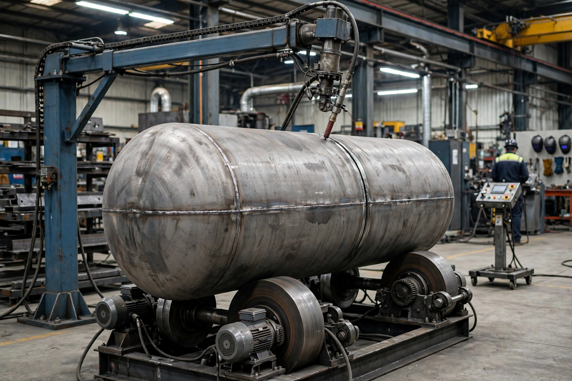
A welding rotator is a set of powered turning rolls that supports a cylindrical workpiece and rotates it at a controlled speed under a stationary welding torch, so a circumferential seam can be welded continuously in the flat position.
That one sentence decides almost everything else in this guide. A rotator does not tilt the workpiece. It does not grip it in a chuck. It supports it on rollers and turns it by friction. If your workpiece is cylindrical, can sit on rollers, and needs a circumferential weld, a rotator is usually the right machine. If it is offset, flanged, or non-cylindrical and needs to be clamped and tilted, you probably need a positioner instead.
Short Answer
Put the vessel on the rolls, set the speed, and let the joint come to the torch.
A typical rotator set has two units: a powered drive unit and a non-powered idler unit. The cylindrical workpiece — a pipe, tank, shell, pressure vessel, or wind tower section — rests on the rollers of both units. The drive unit turns the workpiece around its longitudinal axis. The torch stays in one place, usually in the flat (1G/1F) downhand position, while the seam rotates underneath it.
That matters because welding in the flat position is faster, easier to control, and more consistent than welding out of position around a fixed vessel. The welder does not have to climb, reposition, or wait for a crane to turn the work. The arc stays on, the travel speed stays steady, and the heat input stays consistent from the root pass to the final pass.
MISA welding rotators and tank turning rolls are engineered for pipes, tanks, shells, pressure vessels, and wind tower sections, with constant-speed rotation, rugged load-bearing construction, and adaptable wheel arrangements.
Why This Topic Matters
Circumferential welding is where a fabrication shop loses time in three places: positioning, rework, and waiting.
Manual positioning means stopping the arc, moving the vessel with a crane, re-setting the joint, and starting again. Each stop is a chance for a start defect, a change in heat input, and a variation in bead profile. Rework after non-destructive testing (NDT) is often traced back to exactly that variation.
A rotator removes most of that handling from the welding cycle. The workpiece turns. The torch does not move. The operator controls speed from a pendant, often remotely, instead of handling a heavy vessel by hand.
MISA states that continuous arc operation with a rotator can improve production efficiency by 30% to 40% for repetitive vessel and pipe welding tasks. Treat that as a MISA claim for repetitive work, not as a guarantee for every shop. The size of the saving depends on how much of your current cycle is positioning and crane waiting, and how much is actual arc time. If arc time already dominates, a rotator will improve quality more than it improves speed. If handling dominates, the saving can be large.
Safety improves for the same reason. Remote control operation and reduced manual handling of heavy materials create a safer working environment and lower operator strain. That is not a side benefit in a shop welding 20-ton, 60-ton, or 200-ton vessels. It is one of the main reasons to automate rotation at all.
Technical Background: How a Welding Rotator Works
The drive unit and the idler unit
A rotator set is usually sold as a drive unit plus one or more idler units. The drive unit has motorised rollers. The idler unit has free-rolling rollers on an adjustable base frame. Together they support the workpiece at two or more points along its length.
The drive unit rotates the workpiece through direct friction contact between the motorised roller system and the vessel surface. The idler unit provides support and balance. There is no faceplate, no chuck, and no tilt axis. That is the difference that matters, and it is also the limit: if the outside diameter cannot maintain friction contact with the rollers, the rotator cannot turn it reliably.
Speed is controlled by a variable-frequency drive (VFD). The VFD gives stepless, smooth speed adjustment, which is critical for maintaining a consistent weld pool. If speed varies, heat input varies, and bead height and penetration vary with it. Industry guides commonly quote surface speeds in the range of 100 to 1,200 mm/min for turning rolls, with the exact range depending on process, wall thickness, and joint. Older Weld-Fab instruction material gives the same range in different units: a linear workpiece speed of 6 to 60 m/h. Use those figures as typical ranges, not as a specification for a particular MISA model. Final speed, torque, and drive ratio are specified per project.
Why flat-position welding changes the result
When a cylindrical workpiece rotates under a stationary torch, the weld pool stays in the flat position for the whole circumferential seam. The torch can use submerged arc welding (SAW), gas metal arc welding (GMAW/MIG), or gas tungsten arc welding (GTAW/TIG), and the deposition rate can be matched to a constant rotation speed.
That is the technical reason a rotator improves quality, not just speed. Uniform rotational speed helps maintain consistent heat input and weld continuity, supporting compliance with AWS and ISO quality expectations. A manual weld around a fixed vessel, by contrast, forces the welder through flat, horizontal, vertical, and overhead positions in a single seam, each with a different deposition rate and a different risk of defect.
What a rotator is not
A rotator is not a positioner, and it is not a manipulator. The three machines solve the same basic problem — getting the joint into the right position — in different ways. Confusing them is the most expensive mistake in this article, so the comparison table in the next section is the one to read first if you read nothing else.
Main Comparison / Selection Logic: Rotator vs Positioner vs Manipulator
This table matters because it stops the reader buying the wrong family of machine. Price and tonnage do not decide the family. Geometry and how the workpiece is held decide it.
| Machine | What moves | How the workpiece is held / driven | Best for | Wrong choice when |
|---|---|---|---|---|
| Welding rotator (turning rolls) | Workpiece, supported and rotated only | By friction between the outside diameter and driven rolls; no grip, no tilt | Cylindrical work: pipes, tanks, shells, pressure vessels, wind tower sections; circumferential seams | The section is non-cylindrical, tapered without adjustment, or varies in diameter so the rolls lose contact |
| Welding positioner | Workpiece, gripped, rotated, and tilted | Positively, via faceplate, chuck, or between headstock and tailstock | Flanged, asymmetric, or complex work that must be clamped and brought to the flat position | The part is long and unsupported — one-end gripping creates a cantilever load |
| Column-and-boom manipulator | Welding head, not the workpiece | Torch is carried on a vertical column and horizontal boom; workpiece stays put | Large or heavy work that cannot practically be rotated or repositioned; long longitudinal seams | The joint needs the workpiece to turn, and the torch alone cannot bring it to the flat position |
| Floor turntable | Workpiece, on a faceplate, rotated about a vertical axis | Carried on a face, load runs down through a vertical axis | Heavy, any-shape work loaded from above; disc, ring, flange, or vessel-head work welded flat | The joint also needs to be tilted into the flat — a turntable has no tilt axis |
After the table, the conclusion is simple: ask first how the workpiece must be held, and only then how heavy it is. A rotator depends on contact between the workpiece outside diameter and its rolls. A positioner grips the workpiece and drives it positively. That is why a rotator cannot reliably turn an irregular or variable-diameter section, and why a positioner or a headstock-and-tailstock arrangement is the correct answer in that case — not because one machine is better, but because the drive principle is different.
In practice the machines are often used together. A rotator turns the vessel. A column-and-boom manipulator carries the torch over the seam. Together they weld longitudinal and circumferential seams without a crane lift. MISA rotators are designed to connect with manipulators, gantries, and other automation systems for higher-throughput welding cells, and MISA manipulators offer PLC-programmable synchronisation with rotators and positioners.
For pipe spool work, the geometry-first rule is even shorter: for pipe that is supported, cylindrical, and able to turn, use a rotator. When pipe is clamped, use a positioner. When pipe is fixed, use an orbital system. That rule comes from a pipe spool guide, and it is a useful check before any quotation.
Types of Welding Rotator
There are two main types, plus two special types for fit-up and drift control. The difference is how they accommodate a change in workpiece diameter.
Self-aligning rotator
A self-aligning rotator mounts each roller on a pivoting arm. When a workpiece is lowered onto the machine, its own weight forces the arms apart or draws them together until the rollers contact the surface tangentially. The load settles into a stable, centred position without operator input, and the same machine covers a wide diameter range.
The practical consequence is that diameter changeover becomes a lifting operation rather than an adjustment operation. You do not stop to move roller housings, re-check spacing, and verify centre height. You load the next vessel and rotate.
Self-aligning rotators are the right choice when your shop handles varying diameters frequently, when vessels are thin-walled and need even load distribution across multiple wheel contacts, and when changeover time matters more than maximum rigidity. MISA's MSAR series is the self-aligning family. As a MISA-published example, the MSAR-60 is listed as a 60-ton drive-and-idler set with a 750 to 4,500 mm diameter range. Treat that as a model example, not as a specification for every self-aligning rotator.
Conventional / adjustable rotator
A conventional rotator holds a fixed roller spacing. The distance between rollers is set manually — by slotted bolt holes, lead screws, or motorised slides — for a defined diameter band, and changed only by mechanical means when the diameter changes.
Conventional rotators are more rigid, and they are the right choice for very heavy tonnages, thick-walled vessels, and conical sections where independent wheel height adjustment is needed to level the joint. They are also the right choice when the same diameter is repeated for a long run, so the setup cost is spread over many identical vessels.
MISA's MCR series is the conventional family. Older Weld-Fab project material lists conventional rotators from 5 tons to 200 tons in a single order, which shows the range, but it does not mean every conventional model covers that whole range.
Fit-up and anti-drift rotators
A fit-up rotator is designed to align and fit up workpieces before welding, often as part of a fit-up pipe growing line. Hydraulic cylinders shift the vessel vertically, horizontally, and axially to align seams before the circumferential weld.
An anti-drift rotator adds sensor-based feedback. A displacement sensor monitors the edge of the vessel. If drift is detected, the drive rollers are tilted or shifted by a motorised actuator to counteract the movement. Drift matters because a vessel that creeps axially during a long SAW pass will move the joint away from the torch, and the weld will not stay on the seam.
The table below compares the two main types directly. Read it as a choice by changeover frequency and load, not by which type is newer.
This table matters because the two types look similar in a photograph and very different in a working day. One saves setup time. The other saves rigidity at extreme load.
| Criterion | Self-aligning rotator | Conventional rotator | Buyer conclusion |
|---|---|---|---|
| Diameter range per setup | Wide range; arms follow the workpiece | Narrow band; repositioning required between sizes | Frequent diameter changes favour self-aligning |
| Changeover effort | Load and rotate; centring is automatic | Manual adjustment of roller spacing, then verification | If you change diameter several times a day, self-aligning pays for itself in saved setup |
| Load distribution | Even across multiple wheel contacts; good for thin-wall vessels | Rigid frame; good for very heavy, thick-wall vessels | Thin-wall and ovality risk favour self-aligning; extreme point load favours conventional |
| Conical sections | Limited; arms follow diameter but do not level a cone independently | Independent wheel height adjustment can level a conical joint | Conical work needs conventional adjustment, or a purpose-designed fit-up rotator |
| Cost and complexity | More moving parts in the pivoting arms | Simpler, more robust frame | Do not pay for self-aligning flexibility if you weld one diameter all year |
After the table, the conclusion is: choose self-aligning for versatility and changeover, choose conventional for rigidity and extreme load. If you are not sure which matters more in your shop, count how many different diameters you weld in a typical week. That number is the answer.
Worked example: how long does one circumferential pass take?
This is an example with stated assumptions, not a MISA guarantee. Use your own diameter and speed in its place.
Take a vessel 3,000 mm in diameter. Its circumference is about 9.42 m (π × 3 m).
At a surface speed of 300 mm/min, one full circumferential pass takes about 31 minutes: 9,420 mm divided by 300 mm/min. At 600 mm/min, the same pass takes about 16 minutes.
That calculation shows why speed control matters more than top speed. Doubling the speed halves the pass time, but it also halves the heat input per unit length if wire feed and current do not change. The correct speed is the speed that matches your weld procedure — process, wire, current, and wall thickness — not the fastest speed the rotator can turn. Ask the supplier for the speed range, and confirm that the VFD can hold that speed steadily under your load, including eccentric loads.
Application Matrix: Which Workpiece Goes on a Rotator?
This table maps workpiece geometry to the equipment route. It matters because it turns the definition into a decision you can apply to the next job on your shop floor.
| Workpiece / application | Recommended route | Why | MISA-relevant option |
|---|---|---|---|
| Straight cylindrical pipe or spool | Welding rotator | Rollers can support and turn it through full rotation | Rotator, drive + idler |
| Pressure vessel, tank, or shell | Welding rotator, plus manipulator for the torch | Circumferential and longitudinal seams, repetitive work, stable flat-position welding | Rotator + column-and-boom manipulator |
| Wind tower section | Welding rotator, plus manipulator | Heavy cylindrical sections, controlled rotation, stable weld access | Rotator + manipulator, with travel trolley where the line needs it |
| Elbow or offset branch assembly | Clamped positioner, or purpose-designed support | Centre of gravity moves through the motion; rollers cannot grip it | Welding positioner, headstock-tailstock where applicable |
| Flanged spool needing reorientation | Welding positioner | Fixture connection, required tilt, and access to each joint | Welding positioner |
| Excavator bucket or other asymmetric fabrication | Welding positioner, L-type or hydraulic | Workpiece must be tilted and rotated to bring each joint to the flat position | Welding positioner, L-type |
| Large flat or structural assembly that cannot be lifted onto rolls | Column-and-boom manipulator, torch moves | Workpiece stays put; torch travels to the joint | Welding manipulator |
| Pipe that cannot rotate | Orbital head or another qualified fixed-pipe process | Head envelope, clamping length, and joint access decide it | Special welding equipment, by project |
After the table, the conclusion is: cylindrical, roller-supported work is rotator work. Offset, flanged, or non-cylindrical work needs a positioner. Work that cannot move at all needs a manipulator to bring the torch to it. If your shop does all three, you do not need three separate decisions — you need one cell layout that lets the rotator, positioner, and manipulator work together, and a supplier who will design that layout with you.
MISA's verified applications include pressure vessel fabrication, tank and shell welding, pipe spool production, wind tower section assembly, marine and shipyard fabrication, and structural steel manufacturing. Those are the applications to use as a check: if your work is not in that list, say so in the RFQ and ask whether a rotator is still the right route.
Cost / ROI / Total Cost Factors
Do not compare rotators by purchase price alone. Compare them by cost per seam, including handling, rework, and crane time.
The table below shows the direction of each cost driver. It is a framework for your own quotation comparison, not a price list. Prices vary by capacity, diameter range, control package, and delivery, and any price quoted without those conditions is not comparable.
| Cost driver | Manual / crane positioning | Rotator, manual welding | Rotator + manipulator, automated cell |
|---|---|---|---|
| Equipment capex | Lowest | Medium | Highest |
| Arc-on time | Lowest; arc stops for every reposition | Higher; continuous rotation | Highest; torch and workpiece move together |
| Labour per seam | Highest; welder waits, crane operator waits | Lower; operator controls speed from pendant | Lowest per seam at volume; operator supervises the cell |
| Rework and NDT failures | Highest; out-of-position variation | Lower; consistent heat input | Lowest; repeatable process, if procedure is correct |
| Crane time | Highest; crane turns the work | Lower; crane only loads and unloads | Lowest; travel trolley can move the vessel along rails |
| Floor space | Lowest | Medium; rotator footprint plus loading space | Highest; cell layout, rails, and manipulator envelope |
| Training and maintenance | Lowest | Medium; VFD, motors, rollers | Highest; PLC, synchronisation, and integration |
After the table, the conclusion is: a rotator pays back when handling time, not arc time, dominates your cycle. If you weld the same diameter repeatedly, a conventional rotator can pay back quickly. If you change diameter frequently, a self-aligning rotator can pay back in saved setup time. If you weld one-off, asymmetric work, a rotator may not pay back at all — a positioner is the better investment.
Work the example in your own numbers. Count seams per week, positioning time per seam, crane time per seam, and rework rate before and after automation. Do not accept a supplier ROI that does not show those four inputs.
When Not to Use a Welding Rotator
A rotator is not the right machine for every welding job. Saying so builds trust, and it saves the cost of a machine that cannot hold the work.
Do not use a standard rotator as the first choice when:
- The workpiece is not cylindrical. A box, frame, or irregular fabrication cannot sit on rollers and turn by friction. It needs to be gripped and tilted by a positioner.
- The workpiece is offset or flanged and the centre of gravity moves outside the roller support. The rotator will slip, stall, or tip the load. A clamped positioner with a defined torque and centre-of-gravity envelope is the safer choice.
- The diameter varies so much along the length that the rollers lose contact. A tapered or stepped vessel needs conventional adjustment, a fit-up rotator, or a positioner — not a standard self-aligning set.
- The surface cannot tolerate roller contact. A polished, coated, or clad surface can be marked or damaged by steel wheels. Ask for polyurethane wheels, or a different holding method, and state the surface sensitivity in the RFQ. MISA offers polyurethane wheels for delicate or coated surfaces, rubber wheels for general use, and steel wheels with optional knurling for increased friction.
- The joint needs to be tilted as well as rotated. A rotator has no tilt axis. If the joint must be brought to the flat position by tilting, a tilt-and-rotate positioner is the correct machine.
- The work must stay fixed. A pipe that cannot rotate, for example because it is already installed or connected, needs an orbital head or another fixed-pipe process, not a rotator.
If any of these apply, the right next step is not a larger rotator. It is a different machine, or a different cell layout. MISA's welding positioner and welding manipulator pages are the starting points for that conversation.
Common Buying Mistakes
- Choosing only by rated tonnage. A 20-ton rotator does not automatically handle every 20-ton vessel safely. Diameter, centre of gravity, eccentricity, wheel contact, and torque can make the same weight unsafe or unusable, leading to slipping, stalling, poor weld quality, or a tipping risk.
- Buying a rotator for a non-cylindrical or offset assembly. The rollers will lose contact, the workpiece will not turn evenly, and the weld will drift off the seam. The cost is not just the wrong machine — it is the rework, the delay, and the second machine you have to buy anyway.
- Ignoring diameter range and wheel contact. A rotator that covers 500 to 3,500 mm will not cover a 4,500 mm vessel, and a rotator set for one diameter will not centre a different diameter without adjustment. If you do not state the full diameter range, you will get a quotation for the wrong range.
- Ignoring wheel material for stainless or coated surfaces. Steel wheels can mark or contaminate a stainless or polished surface. Polyurethane wheels are the standard for delicate surfaces in MISA's options, but they have load and temperature limits. State the surface in the RFQ.
- Ignoring speed control and VFD quality. A rotator that cannot hold a steady surface speed under load will vary heat input and bead profile. That variation shows up as NDT failures, not as a speed specification on the quotation.
- Ignoring voltage, CE marking, and local safety rules. MISA configures electrical systems for 110 V to 600 V, with adaptation to local safety rules, standards, and cable colour conventions. A rotator built for one country's power and safety rules is not automatically compliant in another country. Confirm voltage, documentation, and CE marking before ordering for export.
- Ignoring integration with the manipulator. A rotator and a manipulator that cannot synchronise will not weld a circumferential seam as a cell. They will weld as two separate machines that happen to be in the same shop. Ask for PLC synchronisation where the cell needs it.
- Ignoring floor, rail, and crane access. A rotator needs loading space, a travel path if a trolley is used, and crane capacity to load the heaviest vessel. If the shop floor cannot take the load, or the crane cannot reach the rotator, the machine will sit idle.
- Ordering without a drawing, joint list, or production target. If you do not send the workpiece drawing, the joint types, and how many seams per week you need to weld, the supplier cannot size the drive, the speed range, or the duty cycle. You will get a catalogue recommendation, not a specification for your shop.
Buyer Checklist
- What is the workpiece diameter range, length, and weight? Diameter sets wheel spacing, length sets support spacing, and weight sets drive and frame size. All three are needed; weight alone does not size a rotator.
- Where is the centre of gravity, and how much eccentricity is there? Centre of gravity sets torque, stability, and tipping risk. Eccentric loads, nozzles, and attachments shift the centre during rotation and can stall a drive that was sized for a concentric load.
- What joint types do you need to weld? Circumferential, longitudinal, and fillet joints need different torch access and different rotator and manipulator combinations. List every joint, not just the largest one.
- What weld process will you use? SAW, MIG/MAG, TIG, and FCAW have different travel speeds, heat inputs, and torch access needs. The rotator speed range must match the process, not the other way round.
- What surface speed do you need, and how steady must it be? Speed sets heat input. Ask for the VFD speed range in mm/min, and confirm that the speed can be held steadily under your load.
- Is the workpiece surface delicate, coated, or stainless? Surface sensitivity decides wheel material. Polyurethane protects a delicate surface; steel gives more friction for heavy loads. State the surface in the RFQ.
- What control do you prefer — wired pendant, wireless pendant, or foot switch? MISA offers a wired pendant with a 25-foot cable, a wireless pendant with up to a 300-foot working range, and a foot switch for manual tack welding. Control affects operator position, safety, and cell layout.
- What is your power supply and voltage? MISA configures systems for 110 V to 600 V. State your voltage, frequency, and local safety rules, and confirm CE marking and documentation for export.
- What safety features do you need? Emergency stop, end-stop rollers to prevent vessel movement, overload protection, and remote control all affect safety. Do not assume they are included in every quotation.
- Do you need a travel trolley? A manual or powered trolley under the rotator base can move vessels along rails and reduce crane dependency. It also needs floor space and rails, so decide it before the layout is fixed.
- What existing manipulator, positioner, or rotator do you already have? Integration with existing equipment decides synchronisation, control, and layout. Send the existing model and control type with the RFQ.
- What is your production target — seams per week, and cycle time per seam? Production target decides whether a manual rotator, a semi-automatic set, or a fully integrated cell is the right investment. Without it, ROI cannot be calculated.
What to Send for a Quote
Send MISA the following with your RFQ. The more of it you send, the less the quotation has to guess.
| RFQ field | Why MISA needs it |
|---|---|
| Workpiece diameter range, length, and weight | Sizes drive, frame, wheel spacing, and support spacing |
| Centre of gravity, eccentricity, nozzles, and attachments | Sizes torque and checks stability and tipping risk |
| Joint types and weld positions | Decides rotator vs positioner vs manipulator, and torch access |
| Weld process and power source | Sets speed range, heat input, and synchronisation needs |
| Required surface speed and duty cycle | Sizes VFD, motor, and drive ratio |
| Surface sensitivity — stainless, coated, polished, clad | Decides wheel material |
| Control preference — wired, wireless, foot switch, PLC | Decides pendant, control panel, and cell layout |
| Power supply, voltage, and local safety rules | Decides electrical configuration, CE marking, and documentation |
| Floor space, rail travel, and crane capacity | Checks loading, trolley, and layout are possible |
| Existing equipment on site | Checks integration and synchronisation |
| Production target — seams per week, cycle time | Decides manual vs semi-automatic vs integrated cell, and ROI |
| Drawings, quantity, delivery location and date | Prices the system, not just the rotator |
For the product itself, see MISA's welding rotator page, and for project evidence, see welding rotator projects. For the torch-moving partner machine, see the welding manipulator.
Final Recommendation
A welding rotator is the right machine when your work is cylindrical, can sit on rollers, and needs a circumferential seam welded continuously in the flat position.
Choose the type by changeover, not by catalogue order. Self-aligning if you change diameter frequently. Conventional if you weld very heavy, thick-wall, or conical work and need rigidity. Add a manipulator if the torch also needs to travel. Choose a positioner instead if the work must be gripped and tilted.
Do not order by tonnage alone. Order by diameter range, weight, centre of gravity, joint type, process, speed, wheel material, control, power, and production target — in writing, in the RFQ.
Send MISA your workpiece drawing, joint list, and production target for a rotator recommendation and quotation. Start with the checklist above, and ask for the diameter range, load capacity with margin, speed range, wheel material, control package, voltage, and CE documentation in writing, in the purchase order.
Sources and further reading
- MISA, Welding Rotator — definition, applications, wheel options, power, control, how it works: https://weld-fab.com/welding-rotator/
- MISA, Welding Manipulator — stroke, processes, voltage, control, PLC synchronisation: https://weld-fab.com/welding-manipulator-2/
- MISA, Welding Positioner — gripping alternative to a rotator: https://weld-fab.com/welding-positioner/
- RESIZE, Welding Equipment for Oil and Gas Pipe — geometry-first rotator vs positioner rule: https://resizeweld.com/blog/oil-gas-pipe-welding-equipment/
- Westermans, Positioner vs Rotator vs Column & Boom — what moves, best for, comparison: https://www.westermans.com/knowledgehub/positioning-equipment-compared.aspx
- Bota-Weld, Self-Aligning vs Conventional Welding Rotators Explained — how the two designs work and changeover difference: https://www.bota-weld.com/en/a/news/self-aligning-vs-conventional-welding-rotators.html
MISA's 30–40% efficiency claim and model examples in this article are MISA-published claims and examples for stated conditions. Speed ranges from other suppliers are typical ranges. Confirm capacity, diameter range, speed, voltage, and CE documentation for the exact model you order.
Restored legacy detail
Industrial Welding Rotators for Heavy Fabrication
The Ultimate Guide to Industrial Welding Rotators: Optimizing Productivity for Heavy-Duty Fabrication
The Ultimate Guide to Industrial Welding Rotators: Optimizing Productivity for Heavy-Duty Fabrication
Introduction: The Backbone of Modern Pressure Vessel Fabrication
In the world of heavy-duty metal fabrication, precision is not just a goal—it is a regulatory requirement. Whether you are constructing a wind tower in the North Sea or a high-pressure reactor in a Texas refinery, the integrity of a circumferential weld is paramount. This is where the Welding Rotator (also known as a turning roll) becomes the most critical piece of equipment in the shop.
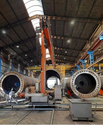
A welding rotator is designed to rotate cylindrical workpieces, such as pipes or large vessels, at a controlled speed under a stationary welding head. This automation significantly reduces welder fatigue, enhances weld bead consistency, and drastically cuts down on fabrication lead times. At Misa Welding(MisaMFG), we understand that selecting the right turning roll configuration—whether it's an Anti-Drift Welding Rotator or a specific Model CR/SAR—is the difference between a high-margin project and a costly rework.
1. Understanding the Core Mechanics: Conventional vs. Self-Aligning
When sourcing a Welding Rotator from China or local suppliers, the first technical decision involves the alignment mechanism.
Welding Rotator Model CR (Conventional Type)
The Model CR (Conventional Rotator) features fixed-center rollers. These are manually adjusted by moving the roller housings along the base frame to accommodate different diameters.
*Best For: Repetitive production of standardized pipe sizes.
*Key Advantage: Exceptional stability for extremely heavy loads (up to 1000 tons).
Welding Rotator Model SAR (Self-Aligning Type)
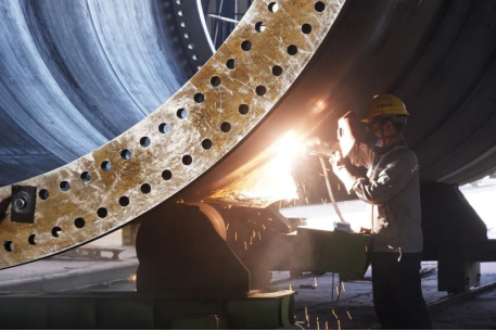
The Model SAR is the industry favorite for versatility. The roller brackets pivot automatically to adjust to the diameter of the vessel without manual intervention.
*Best For: Job shops handling a wide variety of vessel diameters.
*Technical Spec: Features four rollers per section to distribute the load more evenly, reducing the risk of "thin-wall" deformation.
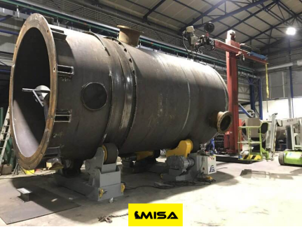
2. Solving the "Spiral" Problem: Anti-Drift Welding Rotator Technology
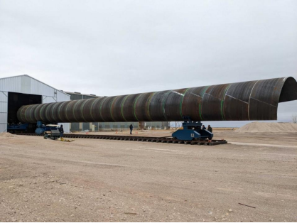
One of the most persistent challenges in long-seam or circumferential welding is axial drifting. As a vessel rotates, minute imperfections in the plate or alignment can cause the cylinder to "creep" or "drift" horizontally along its axis.
An Anti-Drift Welding Rotator solves this through sophisticated sensor-based feedback loops.
*The Mechanism: A displacement sensor monitors the edge of the vessel. If drift is detected, the drive rollers are tilted or shifted by a motorized actuator to counteract the movement.
*Why it matters: For SAW (Submerged Arc Welding) processes, even a 2mm drift can ruin a weld pass. Anti-drift technology ensures the weld head stays perfectly centered on the joint.
3. Precision Assembly: The Fit-Up Welding Rotator
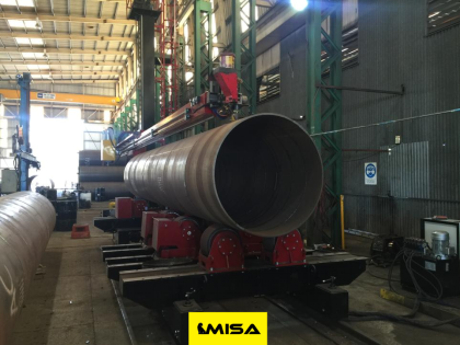
The most labor-intensive part of vessel fabrication is the initial alignment of two cylinders for tack welding. A Fit-up Welding Rotator (often called a "Growing Line" rotator) is designed specifically for this.
These systems allow for:
*Independent Vertical Adjustment: Each roller can be raised or lowered to align the "longitudinal seams" of two pipe sections.
*Hydraulic Manipulation: Utilizing hydraulic power to close the gap between sections for a perfect "root pass" fit-up.
*Application: Essential for wind tower sections and long-distance pipeline manufacturing.
4. Sourcing Strategy: Why "Welding Rotator China" is a Global Standard
For B2B buyers in the US, Canada, and the UK, sourcing a Welding Rotator from China has become the preferred choice due to the maturation of the supply chain. Manufacturers like MisaMFG bridge the gap between high-end Chinese production efficiency and Western quality standards.
Key Buying Criteria for International Shipments:
*Inverter Quality: Ensure the VFD (Variable Frequency Drive) is a reputable brand like Schneider, Siemens, or ABB for local serviceability.
*Polyurethane vs. Steel Rollers: PU rollers provide better grip and protect stainless steel surfaces from carbon contamination, while steel rollers are required for high-temperature or extreme-weight applications.
*Certifications: Always verify CE, UL, or CSA compliance for the electrical cabinets to meet local safety codes in North America and Europe.
5. Technical Specifications Table (Example for Model CR/SAR)
|
Feature |
Conventional (Model CR) |
Self-Aligning (Model SAR) |
|
Diameter Range |
Manual Adjustment |
Automatic Self-Adjustment |
|
Load Capacity |
5T - 1200T |
5T - 500T |
|
Drive Type |
Dual Motor / AC Inverter |
Dual Motor / AC Inverter |
|
Roller Material |
PU or Steel |
PU or Steel |
|
Best Use Case |
Heavy Wall Pressure Vessels |
Thin Wall / Variable Diameter |
6. Maintenance and Safety: Maximizing Equipment Life
To ensure your Welding Rotator lasts 15+ years in a harsh shop environment:
*Lubrication: Weekly greasing of the lead screws and pivot points.
*Earth Grounding: Ensure the rotator has a dedicated "Welding Earth" (Grounding) brush. Without this, the welding current will pass through the bearings, causing "pitting" and premature failure.
*Load Balancing: Never exceed the "Center of Gravity" limits. Even if a rotator can carry 100 tons, an unbalanced load can cause "surging," leading to inconsistent weld speeds.
Conclusion: Elevate Your Production with Misa Welding Investing in a high-quality Welding Rotator is an investment in your shop’s throughput. From the versatility of the Model CR/SAR to the precision of an Anti-Drift Welding Rotator, these tools are the silent partners in every perfect weld.
At Misa Manufacturing, we specialize in providing the technical expertise and the rugged equipment needed for the world’s most demanding fabrication projects.Looking for a quote on a custom Fit-up Welding Rotator? Visit www.misamfg.com to consult with our engineering team today.